7.6.2. Listing of all possible features in the "3D history " docking window 7.6.2.2.
Fixed
plane
|  |
| Prev | Next |
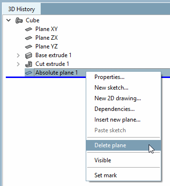
It is called up at the top level using the context menu command Insert absolute level.... [Insert Fixed plane...] The command is only available at component level.
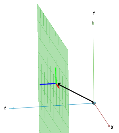
Example of a displacement plus rotation:
If, for example, a connection point shall have another orientation of coordinate system than the original, this can be achieved by a fixed plane.
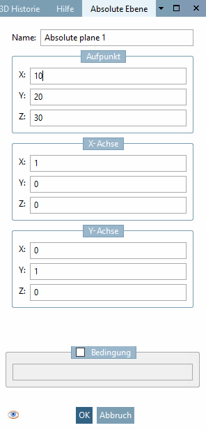
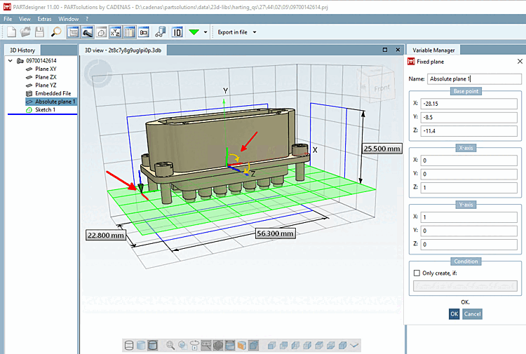
In the example in the following illustration, the original X-axis [X axis] is placed on the Z-axis (Z=1) and then the original Y-axis [Y axis] is placed on the X-axis (X=1). Connection points set by default on the absolute plane now have the new orientation.
![[Note]](https://webapi.partcommunity.com/service/help/latest/pages/cn/3dfindit/doc/images/note.png)