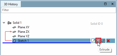
Call: Solids [Base] > Extrude...
→ The sketch is displayed in the 3D view
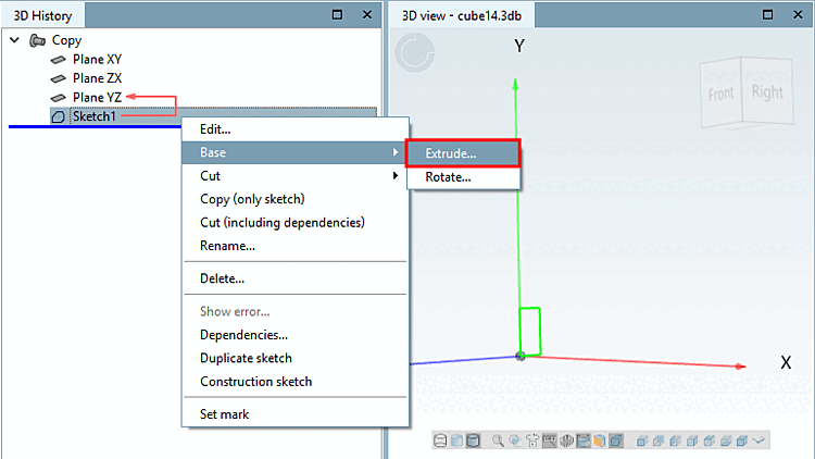
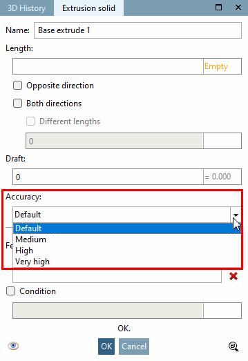
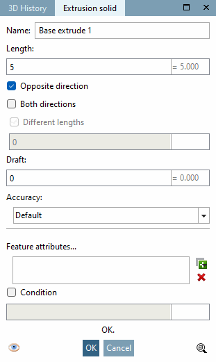
→ The Extrude... command opens the Extrusion object [Extrusion solid] dialog box.
![[Note]](https://webapi.partcommunity.com/service/help/latest/pages/cn/3dfindit/doc/images/note.png)
As soon as complete entries have been made, a preview appears in the 3D view and changes are displayed immediately.
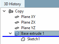
Name: "Base extrude <number>" appears by default. The number is incremented with each extrusion.
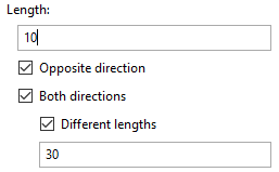
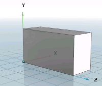
In the Length field, you define the extent of the 2D object.
Opposite direction extrusion is carried out in the opposite direction.
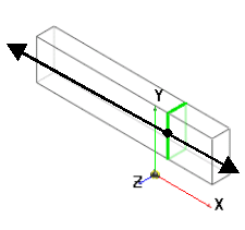
Both directions: The extrusion is performed in both directions.
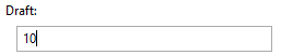
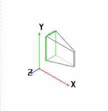
Shaped be [Draft] velto create a bevel from the 2D sketch, enter the corresponding angle dimension in the Shape bevel field.
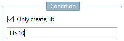
You can also link each extrusion to a condition [Condition] condition. Possible characters are &, |, !=, =, >, <, >= and <=.
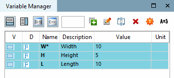
Example: The sketch should only be extruded if for variable H (height) a value larger than 10 has been set.
Design steps (features) that are excluded due to the condition are shown deactivated in the 3D history [3D History] and marked with an if symbol (
 for Base
  for Cut).
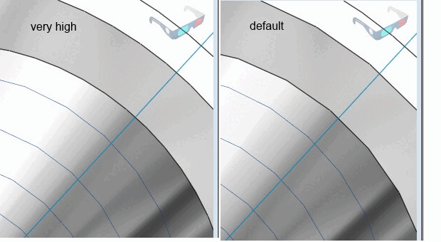
Minimal rasterization [Minimum rasterization]:
In some rare situations, it may be necessary to increase the accuracy for the minimum rasterization within a part for a specific feature in order to be able to create a specific geometry. You will find this setting option under Solids [Base], Cut and Sweep.
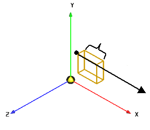
![Black vector = direction: against surface normal [Against surface normal]](https://webapi.partcommunity.com/service/help/latest/pages/cn/3dfindit/doc/resources/img/img_c80a61e4e1b547daa4bc85f4fe36ac0a.png)
![Black vector = direction: both directions [Both directions]](https://webapi.partcommunity.com/service/help/latest/pages/cn/3dfindit/doc/resources/img/img_d36353949f96466080a7c84a99627525.png)