1.3.4.7.2.  Example "Drawing a hand wheel"

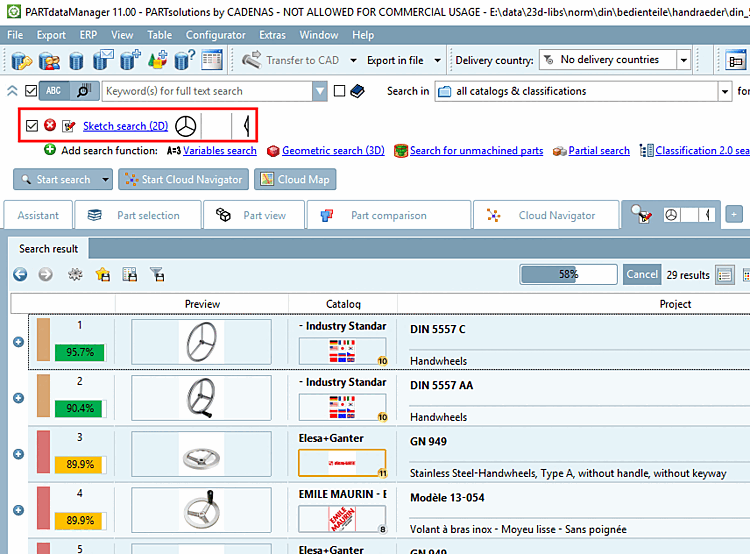
In the following a hand wheel is drawn and all needed steps explained in detail:

  1. Draw the first view on the front cube face. When clicking on another cube face, you can turn it in the foreground anytime and then edit.

    Draw first view

    Draw first view

  2. Select the color for drawing.

  3. Select Draw ellipse.

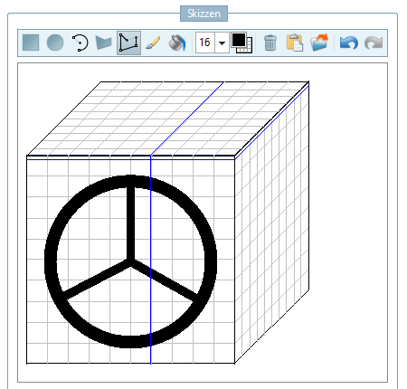
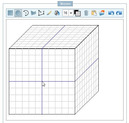
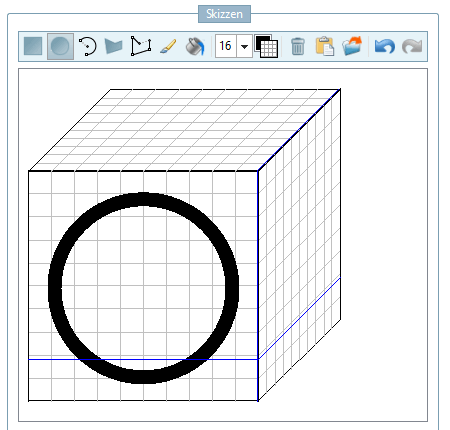
  4. With the left mouse key, click on the center of the drawing and with held Ctrl key, draw a black circle.

    Draw black circle.

    Draw black circle.

  5. Click on Select deletion color [Choose erasing color].

    Erasing color selected

    Erasing color selected

  6. Leave the already selected circle function.

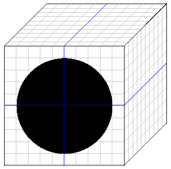
  7. With the left mouse key, click into the center of the drawing again. Once you are close to a snap point it displays.

    Click on the snap point and with held Ctrl key, draw a smaller white circle.

    Draw white circle

    Draw white circle

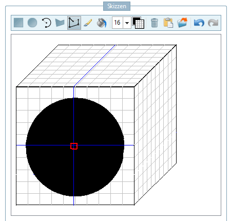
  8. Once again click Choose color for painting.

    Select black

    Select black

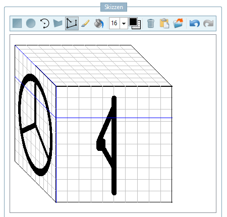
  9. Click on the Draw polygon course [Draw polygon chain] icon.

    [Note]Note

    You can use this function to draw straight lines.

  10. Select the line thickness 16.

  11. Draw the spokes.

  12. Click on the right cube face.

    -> The view turns in the foreground. Now draw the second sketch view. The needed option is already selected.

    Draw second view

    Draw second view

    [Note]Note

    The more characteristic a feature is, the less sketches are needed. The hand wheel for example is so typical that actually one sketch is sufficient.

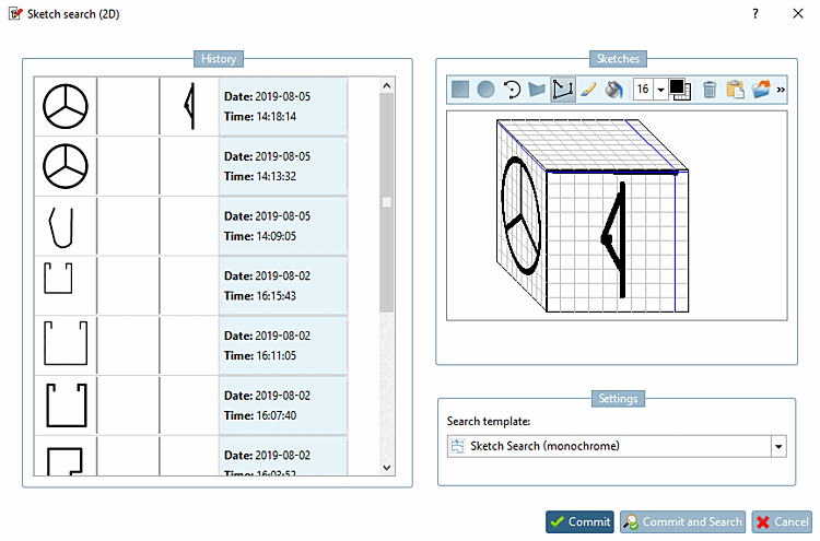
  13. Close the dialog box Sketch search (2D) with Apply [Commit], or Apply and search [Commit and Search].

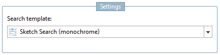
  14. Settings: In the example, select the search template [Search template] "Sketch search (black and white) [Sketch Search (monochrome)] ".

  15. Click the button Start search.

    Search results

    Search results

    -> The search results are listed below.

    Optionally, you can now load parts into the part comparison [Part comparison]. If you move the mouse cursor over a line, various icons appear:

    Open:

    The part is opened in the part view [Part view] of PARTdataManager opened.

    Load as 1st component [Load as first part]:

    The part is added to the part comparison and furthermore marked as first part, thus is loaded into the 2D/3D comparison. The line is marked with an icon .

    Load as 2nd component [Load as second part]:

    The part is added to the part comparison and furthermore marked as second part, thus is loaded into the 2D/3D comparison. The line is marked with an icon .

    Add to component comparison [Add to part compare]:

    The part is added to the part comparison. The line is marked with an icon .

    Transfer to CAD [Export to CAD]:

    The icon is only displayed for individual parts (characteristics), not for part families. Click on the icon to transfer the relevant part to CAD.

    Detailed information on the component comparison [Part comparison] can be found at Section 1.3.10, “ Part comparison.

[Note]Note

The history of created sketches is saved and displayed in the Sketch search (2D) dialog box on the left-hand side. This allows you to use the sketches again at a later date and edit them if necessary.