5.12.11.29.7.2. Connector Symbol (CNSELEK|4)

The symbol assignment is slightly different when classifying a plug, as an extra step is required.

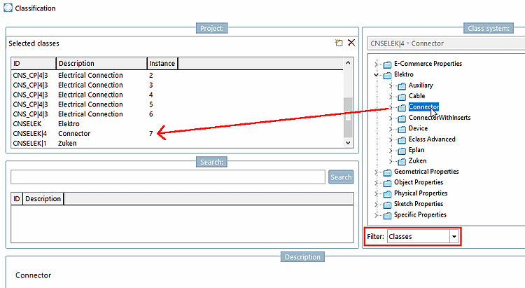
Once all the pins of the connector have been classified (which is done in the same way as for the terminal above), we need to define a symbol that represents the connector as a whole, not just as a collection of pins

Symbol representing the connector

Symbol representing the connector

Each pin of the connector represented separately

Each pin of the connector represented separately

To do this proceed as follows:

  1. Select project to be edited.

  2. Select the General tab page.

  3. Open Classification (CNS).

    -> The Classification dialog box opens.

  4. Select the Classes option under Filter.

    [Note]Note

    To assign a classification to the entire project and not just to individual connection points, this option must be selected.

  5. Double-click Connector.

    -> Connector is displayed under Selected classes.

  6. Open Features (CNS).

  7. Sort by description [Description] and search for Connector Symbol, Connector MasterSymbol and Connector BlockSymbol.

    Enter the desired symbol ID (here S0032) in the Value column according to the following scheme:

Special case

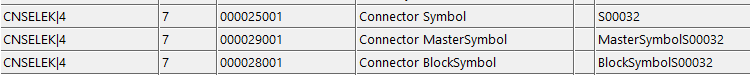
When classifying plugs/connectors and not all connections are of the same type, the modeler himself has to make the decision which connector symbol has to be set globally and adequately for the function of the part.

Example: 10 males and 1 PE connection

Example: 10 males and 1 PE connection

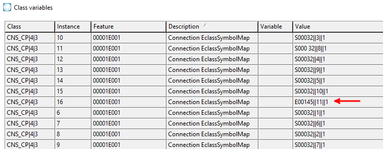
In above case it is clear that S00032 should be set as global symbol.