
To ensure that conversions (of any kind, e.g. PLM-Synchro) from Creo to STEP format run correctly, various things must be taken into account:
If the setting is incorrect, holes, for example, are not displayed correctly and cannot be selected in Partial Search [Partial search], for example.
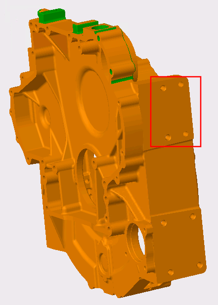
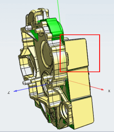
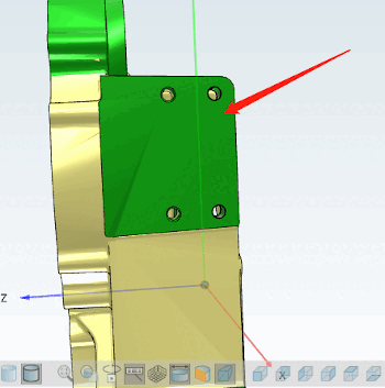
If all settings are made as described in following notes, the individual features will be correctly converted.
The conversion path must be adapted for versions < V11 SP8.
iface.proewildfire,stp,partjava(;ExportTopoFeatures=1)
V11SP4, for example, still has a conversion path [Conversion path]:
iface.proewildfire,stp,partjava
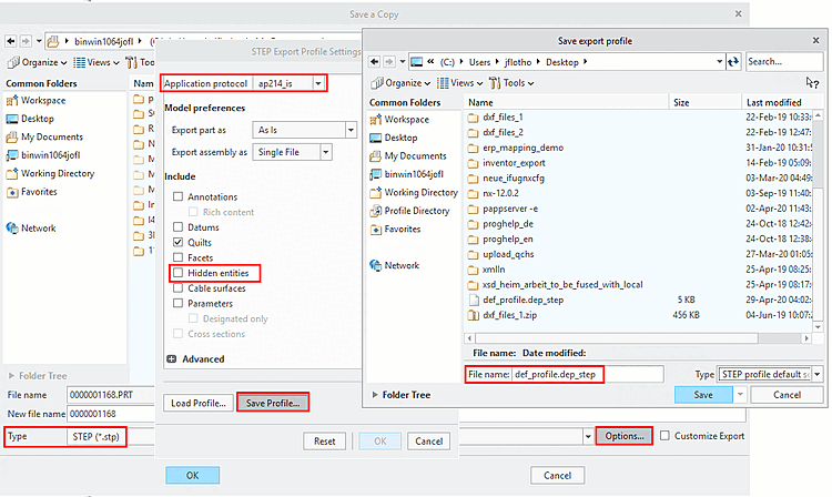
The STEP export profile settings must be set correctly in Creo and the export profile must be entered correctly in
config.pro:Call up the dialog window
STEP Export Profile Settingsvia "File > Save As (Type=STEP ) > ", for example.Under Application log, select the "ap214_is" option and deactivate the Hidden elements option.
Use to save the file
def_profile.dep_stepto a location of your choice (e.g. under C:\Test).Insert the following line with the corresponding storage path in the
config.profile.export_profiles_step C:\Test\def_profile
In the case of PLM Synchro, for example, the run can now be performed.
![Example PLM-Synchro: Node editor [Node Editor] > Conversion path](https://webapi.partcommunity.com/service/help/latest/pages/cn/3dfindit/doc/resources/img/img_c66a320c8b3841abb84305eb4a9e0689.png)
![[Note]](https://webapi.partcommunity.com/service/help/latest/pages/cn/3dfindit/doc/images/note.png)