5.12.11.31. Classify
Electrical Parts - Tutorial 5.12.11.31.2. Defining the
device orientation |  |
| Prev | Next |
Because the model in the project does not necessarily have the correct orientation for the ECAD programs, it must be rotated manually.
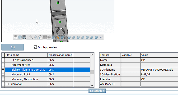
This is achieved by placing a connection point in the 3db (which acts as the origin point of the new coordinate system), which is then classified according to Elektro Alignment Coordsys.
The way in which the component is attached (in real life) defines the orientation of the connection point.
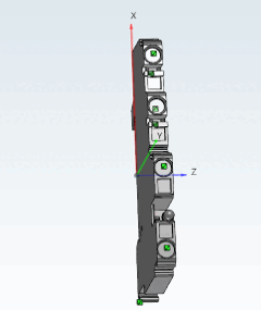
The orientation in the 3db clearly doesn't match the orientation needed for ECAD programs.
The device rotation is done in the following manner:
![[Note]](https://webapi.partcommunity.com/service/help/latest/pages/cn/3dfindit/doc/images/note.png) | Note |
|---|---|
Currently the procedure described in the following has to be done manually; a Wizard for work simplification is under work. | |
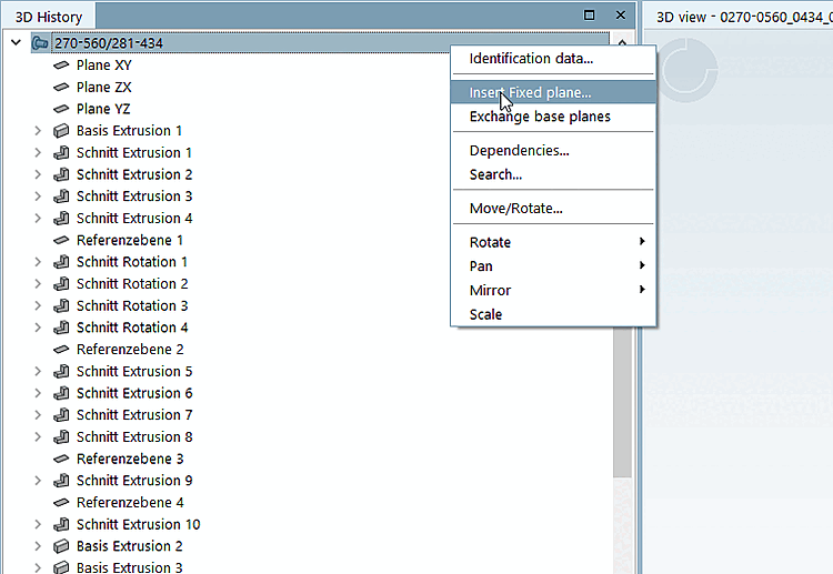
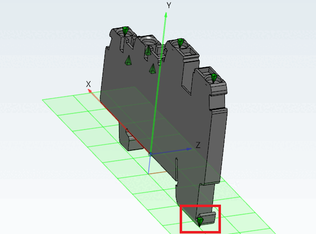
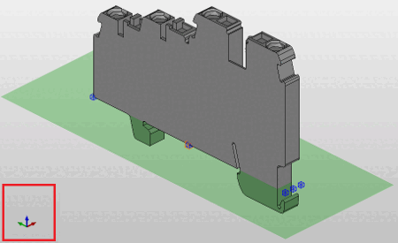
Right-click on the model and select Insert absolute plane.... [Insert Fixed plane...]
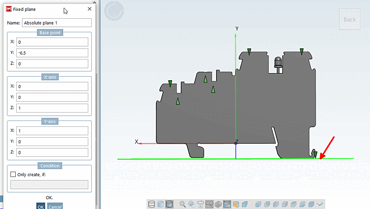
Position the plane on the floor (which will later be the mounting surface in ECAD) so that the outermost point of the part (usually several) touches the plane. The part will therefore not intersect the plane and the corresponding side of the bounding box will correspond to the plane
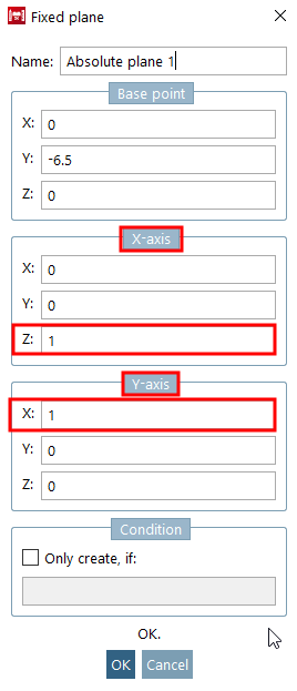
Now you need to define the orientation of the plane according to the observations made in the steps above.
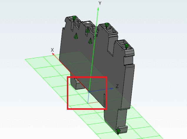
Place a connection point on the already positioned plane.
The point should be at the bottom left of the device, respectively to its mounting orientation. The top of the connection point is showing the direction of the negative Z axis (of the new coordinate system).
Classify the connection point used for orientation as Electrical Alignment Coordsys. Name, identifier, etc. are filled in similarly to electrical connection points.