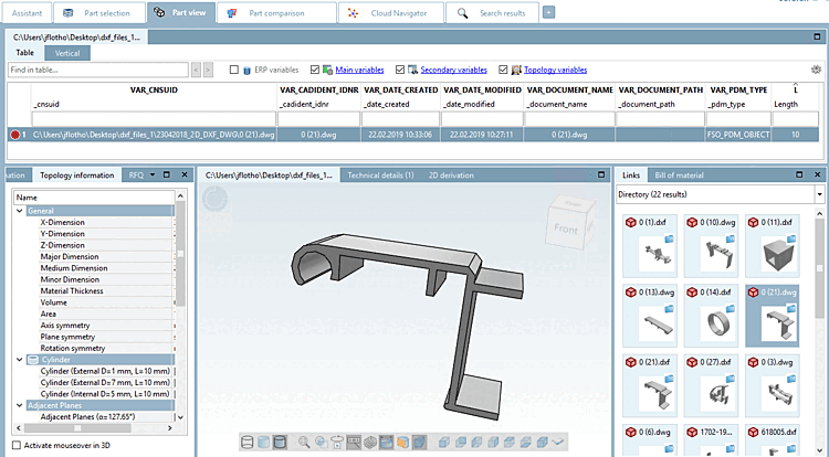
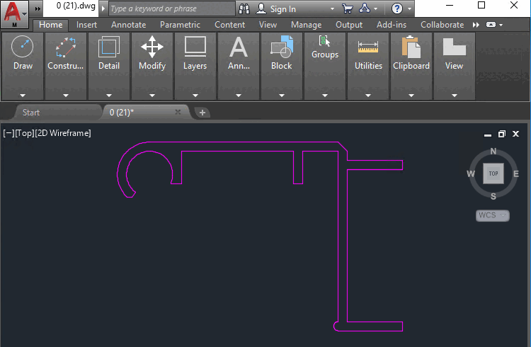
There is a possibility to automatically import DWG/DXF files as 3d geometry. This is interesting for profile manufactures, who only have 2D files but would like to use GeoSearch or provide an eCATALOGsolutions catalog. The function only makes sense for parts which are semi-finished products and are sold by the metre.
The paid license CNS2009*PSADDONS*EXTRUSIONNODEis required:
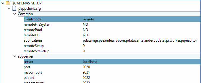
In the configuration file
pappclient.cfgunder blockCommon, set the keyclientmodeto the valueremoteand under blockappserver, set the keyserverto the valuelocalhost.In the configuration file
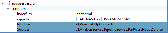
pappserver.cfgunder blockCommon, set the keyModulesto the valueall,PipelineHttpConnectorand the keyServicesto the valueall,AnalysisService,PartWareHouseService,PipelineService.Start the PARTapplicationServer with command input:
C:\CADENAS\SOFTWARE\bin\x86\64\pappserver.exe –e
Create a PLMsynchro pipeline using PLMsynchro Wizard.
See Section 1.2.2, “ Basic setup via wizard”.
The selection at Conversion is irrelevant, as this node is replaced.
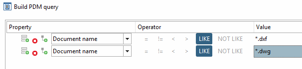
Under Query, select the following setting, for example:
Now the pipeline created by Wizard looks like this:
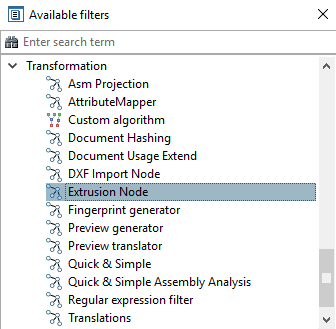
Delete the Conversion node and replace it with Extrusion. You will find the Extrusion node in the Available filters docking window. Simply drag the node into the dialog area of the pipeline and reset the corresponding edges. If necessary, also add the Report node.
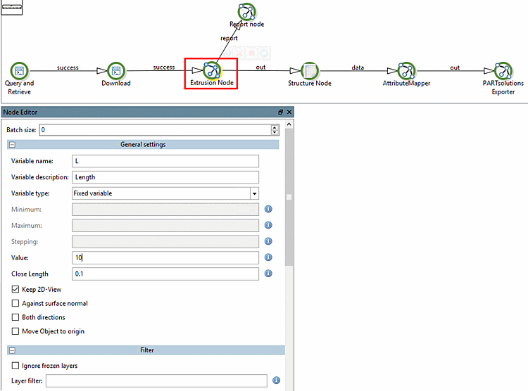
Make the settings for the Extrusion node:
Batch size: The setting is not relevant for the extrusion itself. The extrusion [Extrusion] node can be executed as a 'distributed node'; therefore the option is displayed. The batch size specifies how many tasks are assigned to each client. Leave the default value 0, which means that no fixed value is set.
Variable name: Name of the variable that controls the length of the semi-finished product.
Variable description: Variable description that is displayed below the variable in 3Dfindit.
Minimum (only active if Value range is selected): Minimum value of the value range variable
Maximum (only active if Value range is selected): Maximum value of the value range variable
Step size [Stepping] (only active when Value range is selected): optional
Value (only active if Fixed variable is selected): Variable value for the length of the semi-finished product
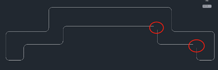
Close Length (default 5): Points are automatically connected up to this distance to create a closed drawing.
Against the surface normal [Against surface normal]: Extrusion is carried out in the opposite direction.
Both directions: Extrusion is carried out in both directions.
Move object towards origin [Move Object to origin]: The bottom left corner of the created 3D object is moved in the direction of the coordinate origin so that the object is not 'somewhere' in space. Depending on the drawing, it could be that the object is slightly away from the origin.
Presently unit cannot be set. If possible, the unit for the created 3db is taken from the drawing. Otherwise per default mm is supposed as unit.
Ignore frozen [Ignore frozen layers] layers: If this option is activated, all frozen layers are ignored during import.
Layer filter: Enter comma-separated layer names that are to be ignored during import. Wildcard * can be used at the beginning of a layer name or at the end or at the beginning and end.
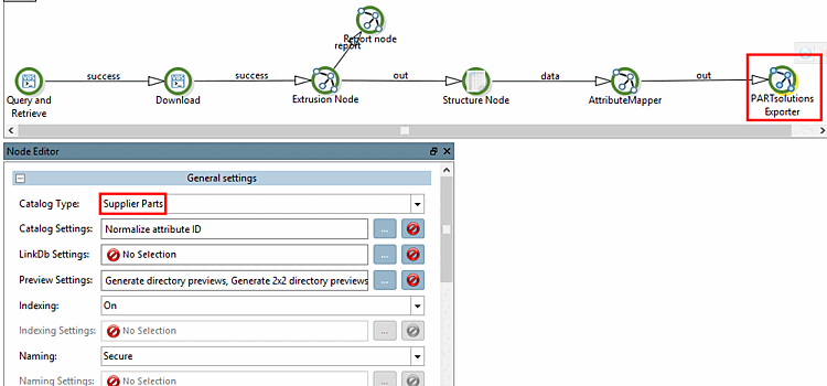
Make the settings for the PARTsolutionsExporter node:
In this example, Catalog Type Supplier Parts is set.
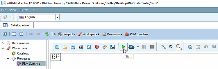
Now click on the Start button
 to execute the PLM Synchro process.
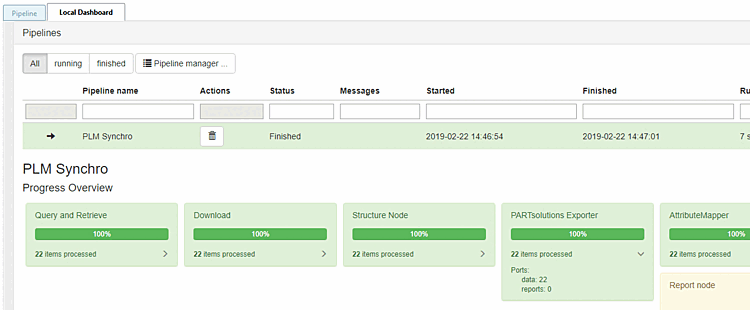
Check the process in the dashboard.
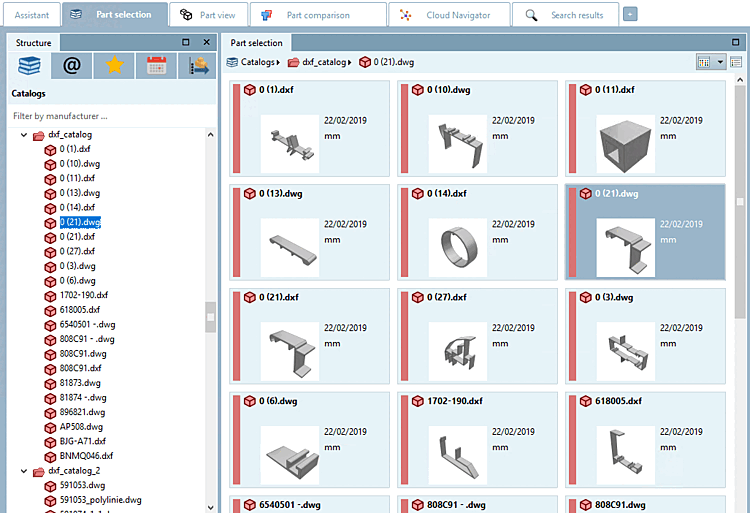
Open 3Dfindit/PARTdataManager to view the result.

![[Note]](https://webapi.partcommunity.com/service/help/latest/pages/cn/3dfindit/doc/images/note.png)