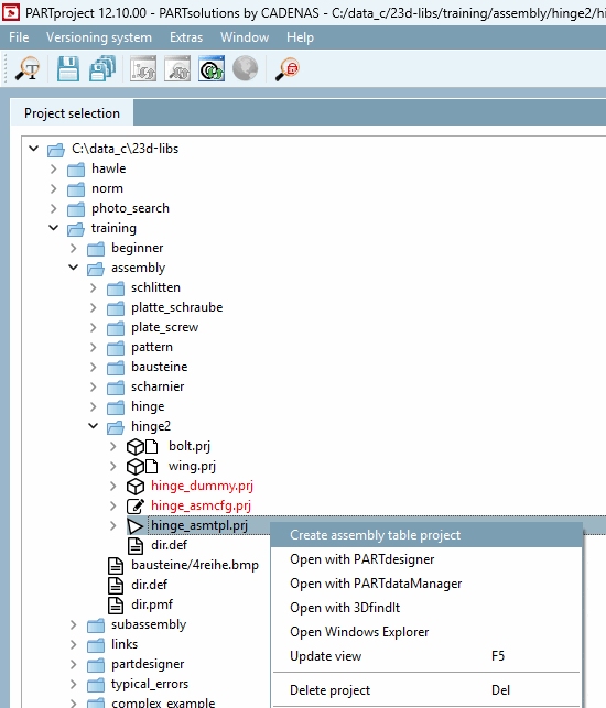
Now create the Assembly Table Project.
Under Project selection -> Context menu of hinge_asmtpl.prj, click on the command Create assembly table project.
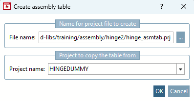
Enter the file name [File name]. This is made up of the project path and a selected name. The target folder can be easily selected using the three dots.
In the list field under Project name, enter the project that contains the table that is to be displayed in the assembly. In our example, this is "HINGEDUMMY". Then click on .
-> The Variable assignment dialog box opens.
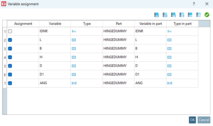
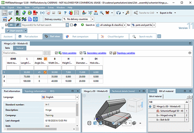
Select the variables to be displayed in the assembly table and confirm with .
Background information: An assembly table has its own table that is being created at this very moment. In the Create assembly table dialog, under Project name, select the component from which the variables for the new assembly table are to be copied; these are then exactly those displayed in the Variable assignment dialog. The new assembly table now has all these values; however, you do not need all of them to define an exact variant in the assembly template/config. Sometimes you only need 1 single variable, for example, and you can then select exactly that variable below. These assigned variables then end up in the assembly table.
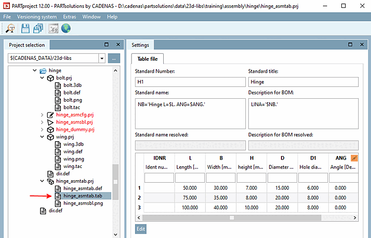
If you have already customized the table of "hinge_dummy.tab/tac", the standard name [Standard name] is correct.
Otherwise assign a unique standard name to the assembly.
So that only the assembly table project is visible in the PARTdataManager and not the "intermediate steps" assembly template and assembly configuration, hide them with Hide project via context menu command of the directory tree. You should also hide the dummy project.
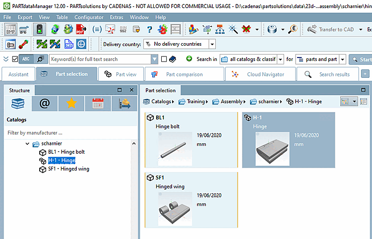
-> The two individual parts "Hinge leaf" and "Hinge pin" and the assembly table project "Hinge" can now be selected in 3Dfindit / PARTdataManager.
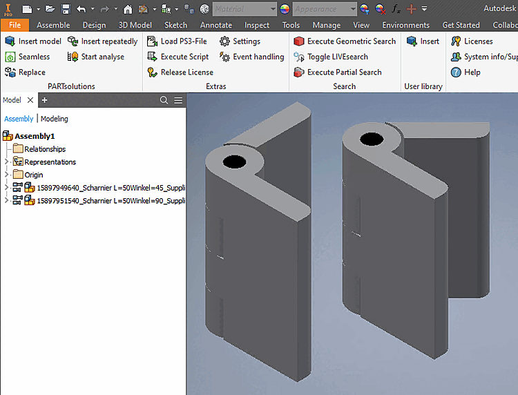
Transfer the assembly to a CAD system (as in the example below with two different angularities).