5.12.11.15. Symbol
representations (Circuit symbols) "Advanced"
5.12.11.15.1. Symbol
representation and its generalization |  |
| Prev | Next |
In this chapter, we have a look on how to create general symbols (circuit symbols), which are specified by the ECLASS symbol representation (AAS425).
When working with symbols we have to differentiate two cases:
Simple symbols (each symbol represents a function):
We consider a model with N functions, where the first function is described by the 3-phase motor with IEC S00836. The other functions can be modeled in any other way.
The relevant classification on the connections looks as follows:
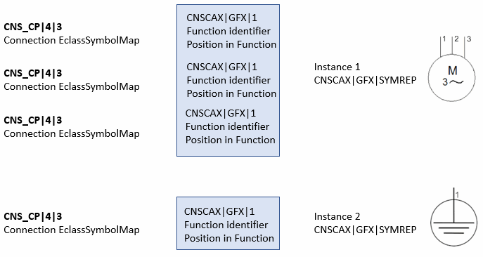
Feature Connection EclassSymbolMap in CNS_CP|4|3 Connection name S00836||1||1 1 S00836||1||2 2 S00836||1||3 3 S00202||2||1 PE A possible symbol representation of the motor with protective earthing using individual IEC symbols (S00836 + S00202): If this situation were to be specifically adapted using the CNSCAX|GFX|SYMREP class, it would be necessary to instantiate two instances of this class. The first instance links to 3 instances of the class CNSCAX|GFX|1 (symbol connection ), the second instance links to one instance of the class CNSCAX|GFX|1. Within all symbol connections, the link to the "real" connection CNS_CP|4|3 is made via the attributes "Function identifier " and "Position in Function ".
Apart from the simplicity offered by such a representation, in many cases, it is intended to flexibly represent the symbols by larger function blocks anyway (here motor + protective earthing). This is achieved by the concept of generalized use of symbols (macro representation) (see next point).
Generalized symbolism (macros):
The following figure shows a possible representation of the combined symbol, which is build by two single symbols according to above functional definition.
Many limitations of the standard symbols are omitted in this way.
There is no limitation concerning mappings between functional and symbol connections. In particular, a macro can graphically represent any number of functional connections of any number of functions.
Let's see the following system:
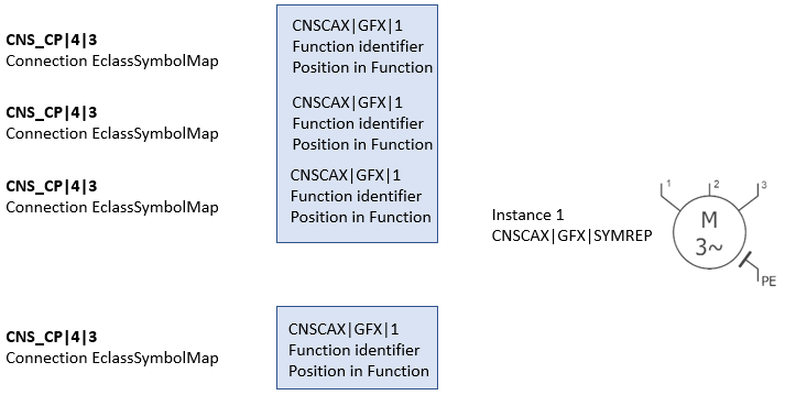
Feature Connection EclassSymbolMap in CNS_CP|4|3 Connection name SYM1||1||1 PE SYM1||2||1 1 SYM1||2||2 2 SYM1||2||3 3 On the one hand the use case in above system is to separately model the functions (PE+Motor) and at the same time to create a clear symbol depiction (suited for the creation of "user friendly" circuits). This means that the system shall be described by differentiated single functions and at the same time it shall be possible to work with the whole function block (Motor+PE).
With the method described above (each function is represented by one symbol) the part would be described by two separated symbols. However, when using macros these limitations are completely omitted. A possible macro representation would be to specify one single symbol for the whole system.
Macro display with single symbol for the entire system. The symbol describes two functions (or their pins) with one instance of CNSCAX|GFX|SYMREP. This means that there is one instance of CNSCAX|GFX|SYMREP that refers to 4 instances of the symbol connections. The linking of symbol connection to real connection is completely analogous to the previous image via the attributes "Function identifier " and "Position in Function ".
This is described in the following example:
We have a system with 12 connections separated in 3 functional blocks. One could describe the system with 3 functions, where the first function has 8 connections, the second 2 and the third 2 as well. Apart from the fact that these 3 functional blocks can hardly be described by the IEC Standard, modelling results in unnecessary complexity. In reality, the model is designed with 10 functions of the type "General device connection" and the IEC symbol "Make-contact" with 2 connections. In the macro, these 3 groups of connections are summarized in clear functional groups.
The figures show both "macro variants" of the system with following characteristics:
Several connections are shown in both variants; look at connection "1", for example.
All possibilities of the IEC symbols still remain; in particular, in the first macro variant the more complex symbol E00106 with 2 connections has been used.
Limitations of the IEC symbols are mostly omitted, while no features get lost.
The user has full control over the symbols' graphical arrangement.
In fact, this a transparent generalization of the so far described IEC symbols.
This demonstrates the high flexibility and freedom for modelling; in particular, the still limited number of IEC symbols can be enhanced. In some planning phases one would like to see all connections at the same time, in others only the just relevant. Furthermore macros offer a great flexibility for the creation of own functions (functional blocks of the total system).
For example, connection 1 exists in both of the following variants.
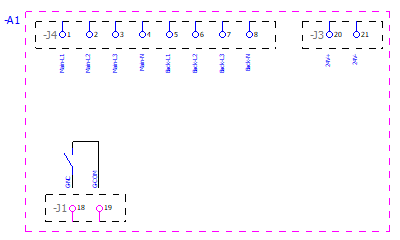
Macro variant 1: The macro contains 3 functional groups. The first group is described by 8 functions with always one connection, the second group by 2 functions with always one connection as well, the third function by the more complex symbol E00106 with 2 connections. The whole macro variant accordingly describes12 connections in one logic, clear entity.
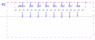
Macro variant 2: In compare to above figure, here, only the first functional block is graphically described. The arrangement of the connections can be performed in any desired way.
![[Note]](https://webapi.partcommunity.com/service/help/latest/pages/cn/ecatalogsolutions/doc/images/note.png) | Note |
|---|---|
In above examples a number of connections have been used double (several times) in the graphics. This is not possible with "pure" IEC symbols. | |