7.13. Docking window "Configurator " / "Assembly " 7.13.6. Docking window "Setup " - Setup configuration
|  |
| Prev | Next |
The docking window Structure [Assembly] is used to select parts or shows the part structure.
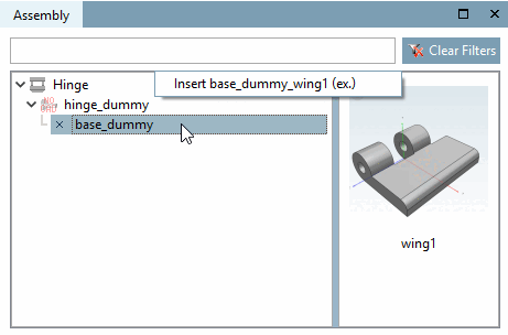
Assembly components can be added at each connection point (x). In the 3D view, these are shown as small green pyramid symbols.
If there are parts available for inserting, the window appears split and the right half shows the possible parts. You can select one with single-click or alternatively via context menu command. If there is only one part available, "(ex.)" with the meaning "exclusive" is displayed behind the part name. If there are several parts available, the addition "(ex.)" is missing.
Build up the configuration by alternating click on listed part and table row (if there is more than one). If there is only one table row, the part is immediately integrated.
When using templates an assembly is immediately loaded, partly or completely. More information on this can be found under Section 7.13.2.1, “Configuration and Template ”.
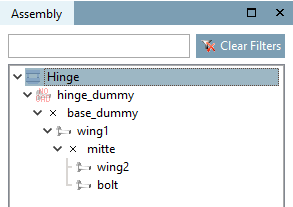
You can see how the single parts are connected among each other.
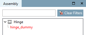
The assembly is shown as root element, below the dummy starter part and the pendent single parts.
If the dummy start part or any individual part is selected, the corresponding table is displayed. If you select different characteristics, the 3D view is automatically adjusted.
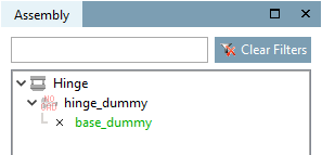
Different text colors bring additional information.
Red: The component is not yet clearly defined. Select a table row.
Green: Parts are available, but none have been selected yet.
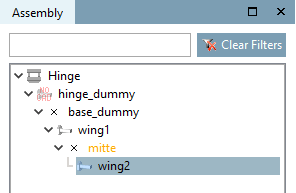
Orange: There is already a part attached, but there are more components available.
Black: The structure is complete.
Gray: Elements shown in this way should not be used to build an assembly, although this is possible in principle.
In fact, such parts can be called and integrated in the assembly, however, their automatic calculation (dimensioning) is not always clear towards starter or neighbor element!
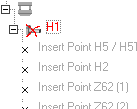
Example: A faulty part is marked with a red X. If the connection points can be calculated anyway, they are depicted in gray text color.