5.12.3.6. Classification
(CNS)
5.12.3.6.7. Visualisation of
diverse auxiliary geometry (spaces) generated from classification
data |  |
| Prev | Next |
In various areas (electrical, piping, BIM, etc.), there is a requirement to mark free spaces in addition to the object to be installed. These can be collision spaces [e.g. for conveyor belts], assembly and maintenance spaces [e.g. for windows, sun protection, boilers] or movement spaces [e.g. in front of/next to sanitary objects such as washbasins, showers]. The visualization of auxiliary geometries is available for individual parts and assemblies.
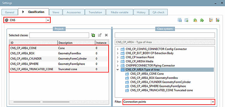
For all these requirements there are some classes in the CNS classification, which create different basic geometric forms:
If
products are equipped with the appropriate class characteristics (in the
rule, this will take place automatically), can be used in 3Dfindit
/ PARTdataManager (or other end media)
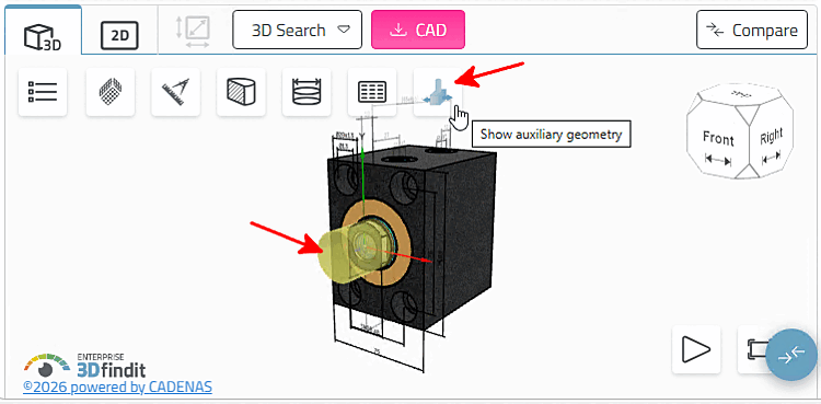
by clicking on Auxiliary Geometry
display [Show auxiliary geometry]
 corresponding rooms visualized in the 3D view
become.
corresponding rooms visualized in the 3D view
become.
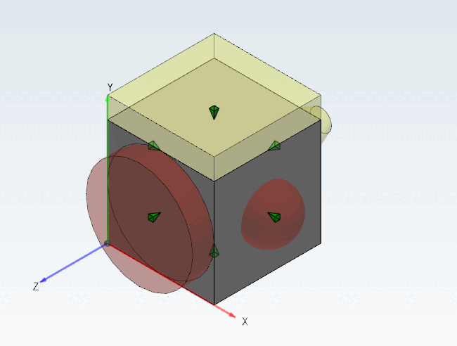
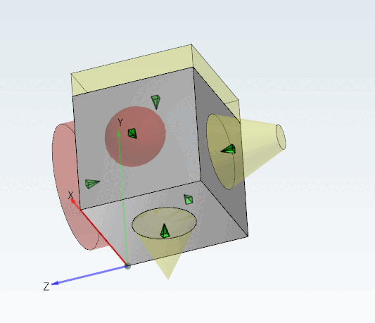
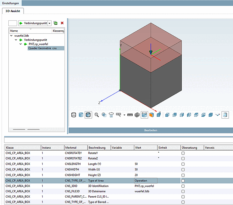
Box (the connection point must be in the center of the base area)
Cylinder (the connection point must be in the center of the base)
Sphere (the connection point must be in the center of the sphere)
Cone (the connection point must be in the center of the base)
Truncated cone (the connection point must be in the center of the base)
For this purpose, the desired class for the creation of a cuboid, cylinder, sphere, cone or obtuse cone is assigned to a certain connection point ( "Connection points [Connection points]"filter [Filter] ) in PARTproject under Type of Area.
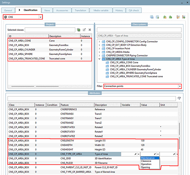
In the Features [Attributes] dialog area, the class features 3D identification and 3D file name [3D filename] must be set as mandatory, otherwise the corresponding parameters for determining the geometry Length (Y), Width (X), Height (Z ) or Diameter in relation to the coordinates of the connection point.
Optionally assign the usage type under Type of Area feature in the list box:
![[Important]](https://webapi.partcommunity.com/service/help/latest/pages/cn/ecatalogsolutions/doc/images/important.png) | Important |
|---|---|
Exception: Cones and truncated cones are only displayed as such if the type of area is also defined. | |
Assign the corresponding ECLASS Advanced usage type properties under the Type of barred area feature.
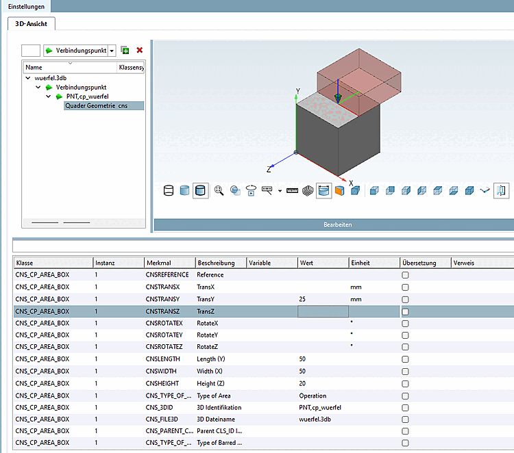
The features TransX, TransY, TransZ, RotateX, RotateY and RotateZ are available for translation and rotation. In the case of translation, the interfering body is shifted according to the axes of the connection point.
The rooms are colored with the $CADENAS_SETUP\partobjects\primitives\primitives.cfg
specified colors.
[Cube_Maintenance]
id=cube_maintenance
file=cube.3db
type=primitive
color=#00cccc

[Cube_Clearance]
id=cube_clearance
file=cube.3db
type=primitive
color=#FFFF66

[Cube_Operation]
id=cube_operation
file=cube.3db
type=primitive
color=#CC2200
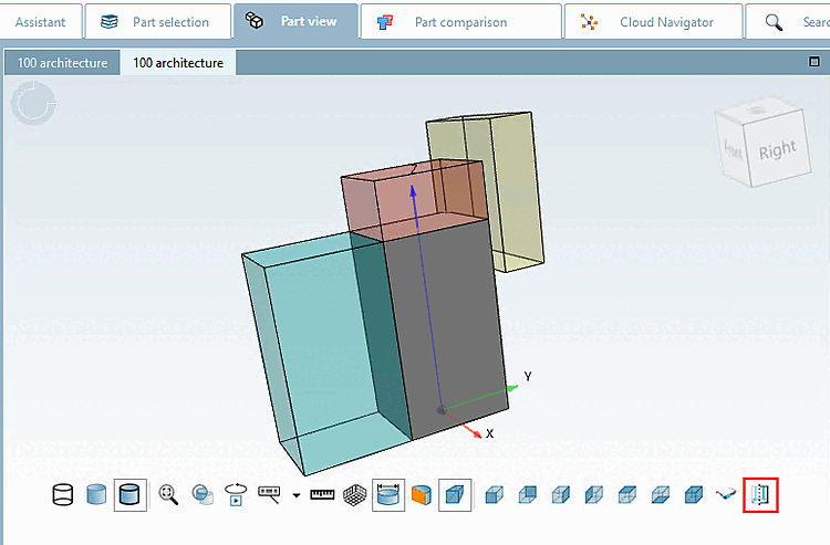
In 3Dfindit, click on the Show auxiliary geometry button to display auxiliary geometries.
If in PARTdataManager the GeometryFormBox option is activated in the 3D view under Classification elements [Classification Elements], the individual class features are displayed.
![Classification elements [Classification Elements] -> GeometryFormBox](https://webapi.partcommunity.com/service/help/latest/pages/cn/ecatalogsolutions/doc/resources/img/img_399c8f10739b48ed9bdf215f97bc13b6.png)
Click on Show auxiliary geometry
the corresponding rooms are visualized.