
Select the part to be classified.
Under Settings, switch to the Classification tab page and then to the 3D view subpage.
Call up the dialog of the same name using the context menu command Select connection point [Choose connection point].
Select the placement connection point and confirm with .
-> The dialog area for published elements [Published elements] is opened.
Activate the Placement Coordinate System class in the CNS classification.
![Select connection point [Choose connection point] (for individual part)](https://webapi.partcommunity.com/service/help/latest/pages/cn/ecatalogsolutions/doc/resources/img/img_53f6ddc703a14bc8b769372b63c536a5.png)
If an assembly is used, the connection point to be used has to be made known to it (meaning which part with which connection point).
![[Note]](https://webapi.partcommunity.com/service/help/latest/pages/cn/ecatalogsolutions/doc/images/note.png) | Note |
|---|---|
Up to and including V11 an assembly's part had to be classified accordingly. As of V12 the respective connection point can be made available on assembly level and be classified directly there. | |
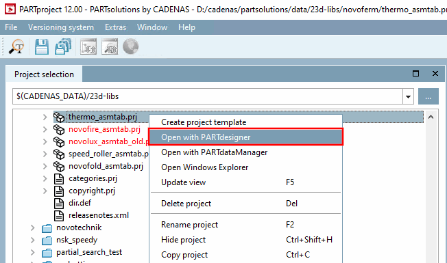
Select the assembly table project (*asmtab.prj) and click the context menu command Open with PARTdesigner.
-> The assembly configuration is opened.
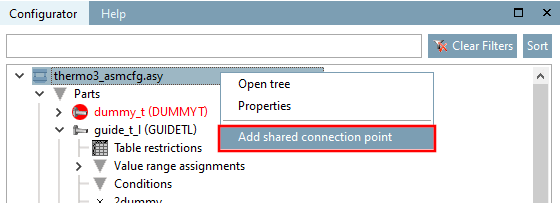
Open the context menu on the main level and click on Add share attachment point [Add shared connection point].
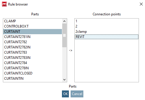
Determine the part and connection point in the rule browser [Rule browser].
-> The shared connection point has been added.
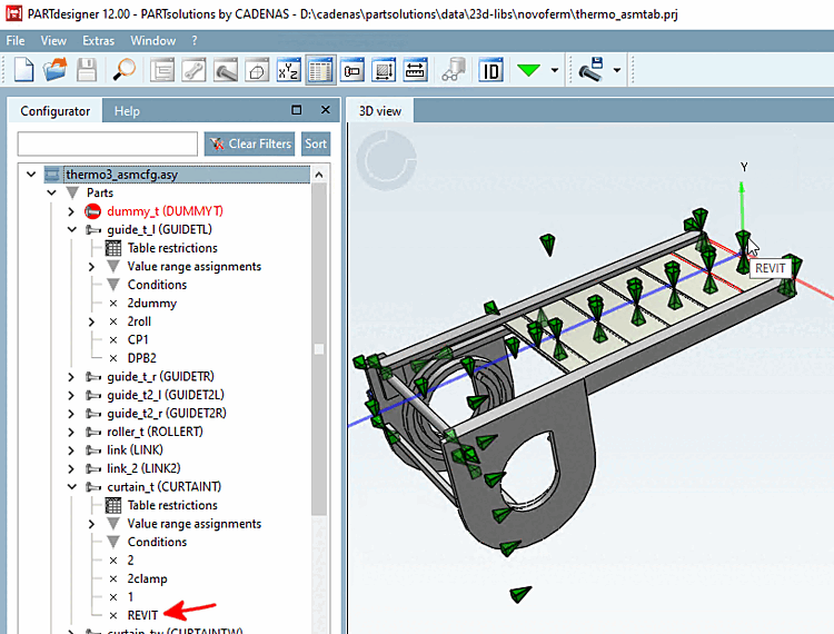
Select the corresponding template file (*.asmtpl.prj) and open the Classification tab page and then the 3D view subpage.
(In the case of assemblies no 3D content is shown.)
-> The shared connection point is displayed in the same-named dialog box.
Select the item and confirm with .
-> Now the standard user interface for the creation of published elements is displayed.
Activate the Placement Coordinate System class in the CNS classification.
![Select connection point [Choose connection point] (for assembly)](https://webapi.partcommunity.com/service/help/latest/pages/cn/ecatalogsolutions/doc/resources/img/img_b01e07ede1854b138cb2596eee44c9bb.png)