1.6. CAD
encompassing reference of all menu commands
1.6.3.
Insert from the standard and purchased parts library via "ENTERPRISE 3Dfindit"
|  |
| Prev | Next |
The following describes how to insert a component from 3Dfindit into your 3D CAD system.
![[Note]](https://webapi.partcommunity.com/service/help/latest/pages/cn/ecatalogsolutions/doc/images/note.png) | Note |
|---|---|
The standard procedure is described. For some CAD systems, you will find further information in the CAD-specific chapter. | |
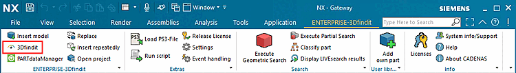
From the 3Dfindit menu, click 3Dfindit
 or Insert Model [Insert model]
 .
.
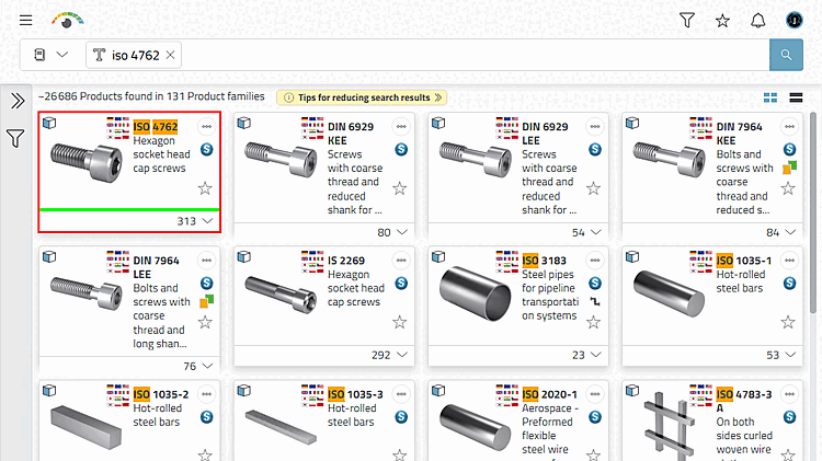
Select the desired component using any search method.
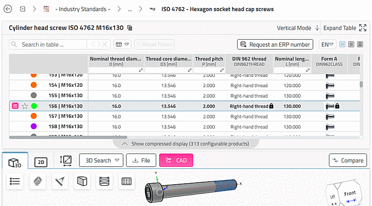
Open the part and determine the desired characteristic.
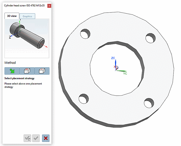
Theplacement dialog appears in the CAD system.

In cylinder bore [In Cylinder] (3Dfindit placement method)
e.g. for placing screws, but also bearings on shafts
Automatically creates the required placement conditions to place the body in a cylindrical hole. [Create automatic references to place a body in a cylinder hole.]
Details can be found at Section 1.6.2.2, “ "In cylinder bore " ”.

On surface (3Dfindit placement method)
Automatically creates the required placement conditions to place the body orthogonally on the surface [Create mates for placement on planar face]
Details can be found at Section 1.6.2.3, “ "On surface " ”.

Touching surfaces [Touching Surfaces] (3Dfindit placement method)
e.g. for the placement of countersunk screws
Placement by means of two contact surfaces [Placement with coincident faces]
Details can be found at Section 1.6.2.4, “ "Surfaces in contact " ”.
-> The 3D view in the placement dialog shows the possible connection points. If several connection points are possible, corresponding information is displayed in the placement dialog.
-> In the placement dialog on the Graphics Tabbed page, you will find 3D images of the component or technical views (if available).
-> The following buttons are displayed in the placement dialog:

Place multiple times [Place multiple] (and leave dialog open) 
Place once (and close dialog) 
Close dialog (without placement) Multiple Place [Multiple placement]: Activating the checkbox allows direct, repeated placement in the CAD, without having to Multiple button place
use [Place multiple].
[11]

If there are patterns in the placement section, these are recognized and a corresponding dialog appears. See Section 1.6.2.5, “ Insert model - Pattern recognition ”.
[11] For certain CAD systems, the Feature available on all placement methods, only on others in the standard CAD placement method. If the method does not lead to is available, then the checkbox appears grayed out.