
Insert all parts into the configuration needed to assemble the hinge.
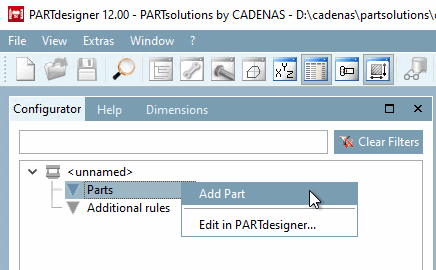
Click on Insert part [Add Part] in the context menu of components [Parts] in the Configurator docking window.
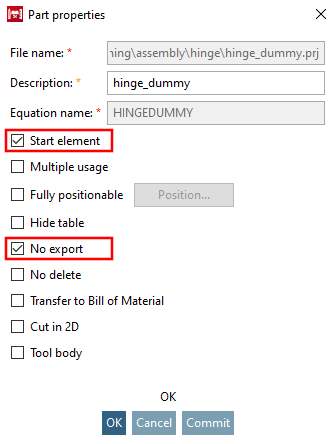
Activate the Start element and Do not export [No export] checkboxes Do not export [No export]
(Please determine the component color in the Docking window Settings > Tabbed page General > Color or preferably under Render properties [Render attributes] ).
→ The component symbol is in the structure tree
 highlighted in red and thus marked as a starting element [Start element].
Insert "fluegel.prj" (leave the default settings in the dialog box).
Insert the "bolzen.prj" (leave the default settings in the dialog box).
After all components have been inserted using the context menu, the following screen appears:
→ The directories Table restrictions, Value range assignments and Conditions are located below the component level.
→ The "x" shows the name of the connection point that was assigned to the part in PARTdesigner.
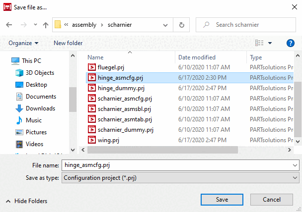
Save the assembly configuration via the File menu → Save .
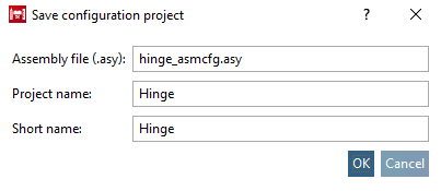
Finally, the Assembly properties dialog box opens.
![[Note]](https://webapi.partcommunity.com/service/help/latest/pages/cn/partsolutions_user/doc/images/note.png)
![Docking window "Configurator [Configurator] "](https://webapi.partcommunity.com/service/help/latest/pages/cn/partsolutions_user/doc/resources/img/img_f0bbaf8ddb024802b40f043e7126b1d0.png)
![Properties [Assembly properties] dialog box of the assembly [Assembly properties]](https://webapi.partcommunity.com/service/help/latest/pages/cn/partsolutions_user/doc/resources/img/img_7fe7f5e4e5f14c31ba4dce2451d2d8fa.png)