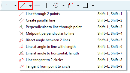
Line through 2 points
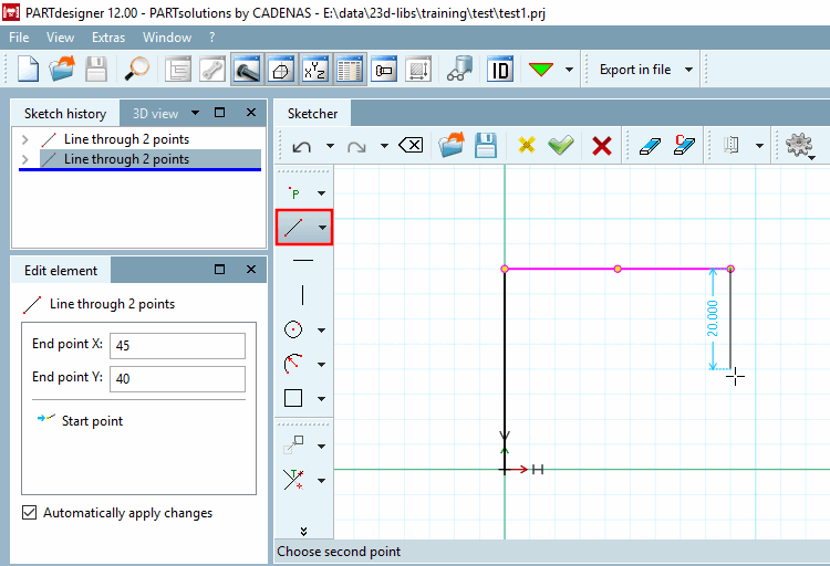
First move the mouse arrow to the desired starting point [Start point] of the line.
Confirm with a single mouse click.
Drag the line to the end point [End point].
-> An auxiliary dimension [Live dimensions] is displayed. You can activate this feature under PARTdesigner -> Extras menu -> Settings [Settings...]... -> Sketcher (hist.) [Sketcher (feat.)] and also set the color. (See Section 7.20.4.2.2, “
Performance
”.)
Fix the line with a single mouse click.
Now edit the point coordinates in the Edit element docking window.
With pressed
Ctrl key, you can continue a polyline with only one click. You don't
have to select the start point of the next line again. In this way you
are much faster.
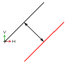
 Create parallel line
Parallels to
an existing line
Click on desired line.
->
Parallel is attached to the cursor.
Fix the parallel at the desired position
with a single mouse click.
If necessary, adjust the distance [Distance] to the starting line in the Edit element docking window.
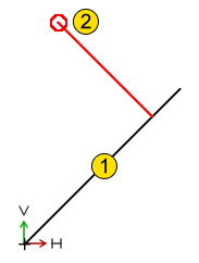
 Perpendicular to line through point
Perpendicular
line to base line
Select the base line [Base line].
-> The
perpendicular line is attached to the cursor.
Determine the end point of the vertical and fix it with a mouse click.
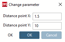
If necessary, adjust the parameters in the Edit element docking window or in the Change parameters [Change parameter] dialog box.
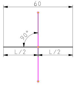
 Midpoint perpendicular to line
Midpoint
perpendicular to base line with same length
Click on the base line.
-> The midpoint perpendicular is set.
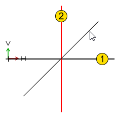
 Angle bisector between two lines
Angle bisector
between two lines
Select the first line.
Select the
second line.
Choose the possible position (variant) of
the bisector (via mouse cursor).
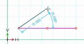
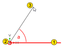
 Line at angle to line with length
Line at angle
"a" with length "L" to any other line
Select base
line.
-> The
line to be positioned is attached to the cursor.
Choose the start
point (does not have to be on the base line!).
Position the end
point.
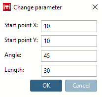
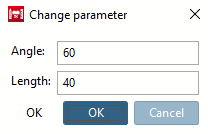
If necessary, adjust the exact angle [Angle] and length [Length] in the Edit element docking window or in the Change parameters [Change parameter] dialog box.
The "Snap to grid" function is not activated for lines at an angle a to lines of length L [Line at angle to line with length] under Quick settings -> Snap to grid, but under PARTdesigner -> Settings [Settings...]... -> Sketcher (hist.) [Sketcher (feat.)] -> Grid -> Scalar parameters. For example, if the width is set to 5, the radius will snap at multiples of 5, regardless of the direction in which you move the mouse.
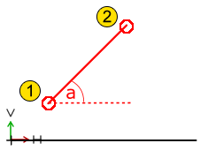
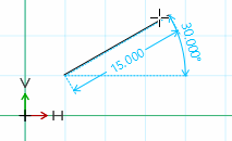
 Line at angle to horizontal, length
Line at angle
"a" to imaginary horizontals
Select start point of line.
Position the end point of line.
If necessary, adjust the starting point [Start point], angle [Angle] and length [Length] in the Edit element docking window or in the Change parameters [Change parameter] dialog box.
The "Snap to grid" function is not activated for lines at an angle a to the horizontal with length L [Line at angle to horizontal, length] under Quick settings -> Snap to grid, but under PARTdesigner -> Settings [Settings...]... -> Sketcher (hist.) [Sketcher (feat.)] -> Grid -> Scalar parameters. For example, if the width is set to 5, the radius will snap at multiples of 5, regardless of the direction in which you move the mouse.
 /
/  Horizontal
Insert [Horizontal line] / Vertical
insert [Vertical line]
Horizontal
Insert [Horizontal line] / Vertical
insert [Vertical line]
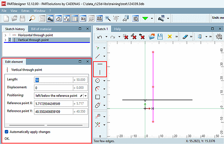
Horizontal or vertical construction line with specified position
Click on
the button.
-> The horizontal/vertical line "hangs" on the cursor.
Click on the desired positioning point (reference point) in the drawing
-> The construction line is inserted.
-> The dialog for Vertical by point [Vertical through point] or Horizontal by point [Horizontal through point] appears in the Edit element docking window.
Set the individual setting options:
Length (default 50): The length of the construction line
Shift [Displacement] (default 0): Shift in the direction of the line
Positioning:
left/below the reference point:
centered to the reference point [centered at reference point]:
right/above the reference point:
centered to the origin [centered to origin]:
Reference point
X: Distance to the zero point in the direction of the X axis
Reference point
Y: Distance to the zero point in the direction of the Y-axis
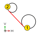
 Line tangent to 2 circles
Tangent line
between two circles or arcs
Select the first circle/arc.
Select the second circle/arc.
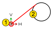
 Tangent from point to circle
Tangential line between a point [Point] and a circle [Circle] or arc [Arc].
Select the start point.
Select the circle/arc [Arc].
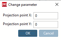
If necessary, adjust the projection point [Projection point] (starting point of the tangent) in the Edit element docking window or in the Change parameters [Change parameter] dialog box.

![[Note]](https://webapi.partcommunity.com/service/help/latest/pages/cn/partsolutions_user/doc/images/note.png)