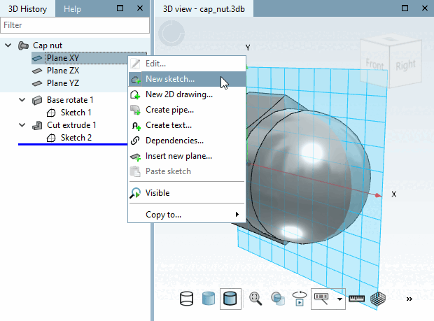
In a last step the cap nut gets an inner thread.
Use the secondary mouse button to call up the context menu for tarpaulin XY.
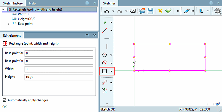
Move the mouse arrow to the coordinate zero point until the snap appears and fix it with a mouse click.
From the coordinate system's zero-point, drag a rectangle and fix it with a mouse click.
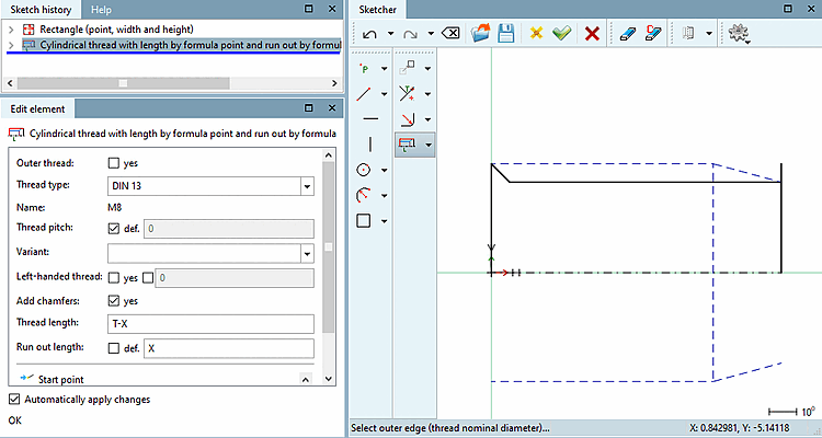
In the Change parameters [Change parameter] dialog box, enter T (thread depth) as the width and DG/2 (nominal thread diameter) as the height and confirm with .
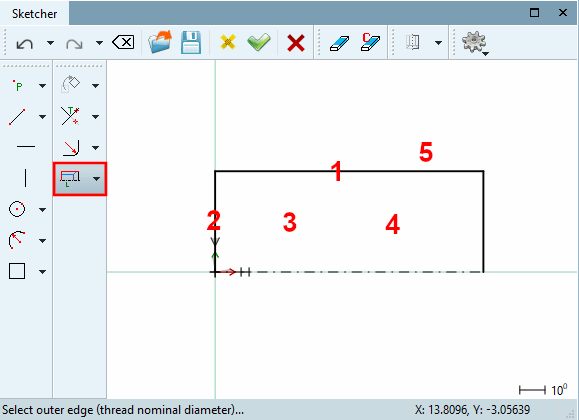
Click the Cylindrical thread over length [Cylindrical thread by length] button
 .
.Click on the corresponding sketch elements and areas and follow the instructions in the footer:
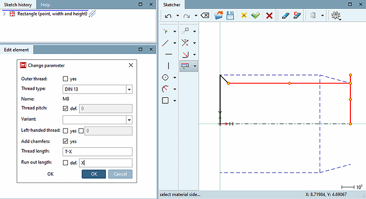
-> The Change parameters [Change parameter] dialog box opens.
Set 'T-X ' for the thread length [Thread length] and 'X' for the run-out length [Run out length] (T = thread depth, X = thread run-out).
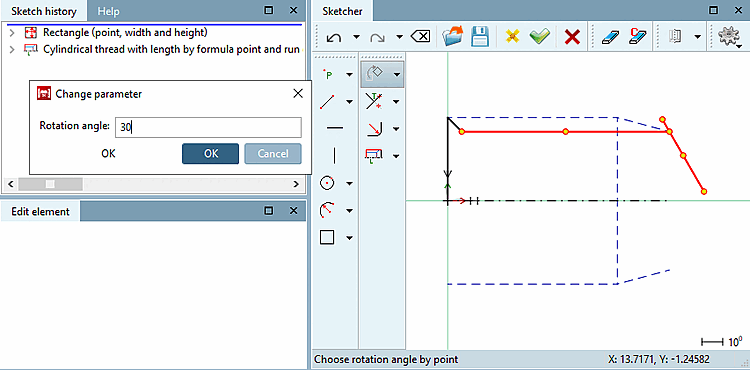
Rotate the right line of rectangle with 30°.
Select the line to be rotated and then click on the Rotate selection button.
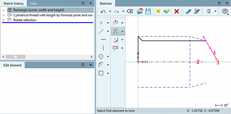
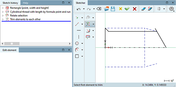
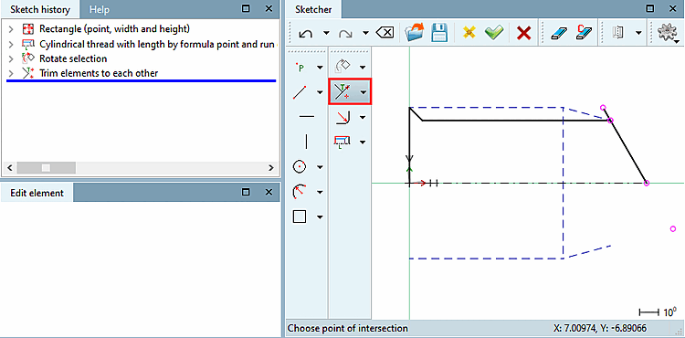
Trim the marked elements to each other in their intersection point.
Click on the Trim elements to each other button
 .
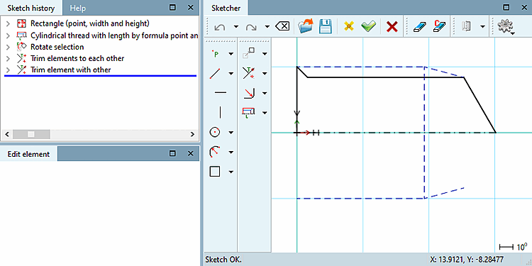
.Remove the protruding line end.
To do this, click on the Trim element to another [Trim element with other] button
 .
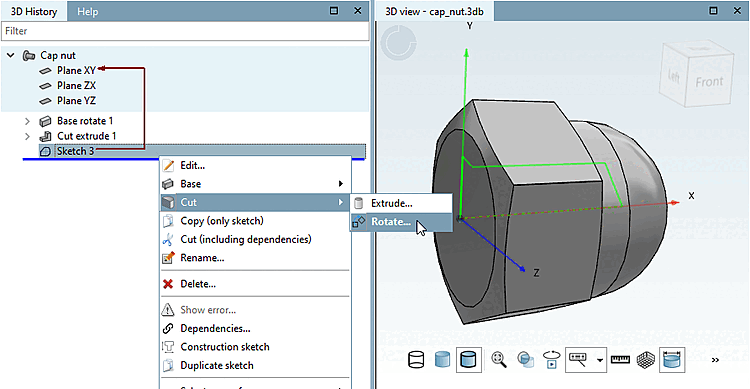
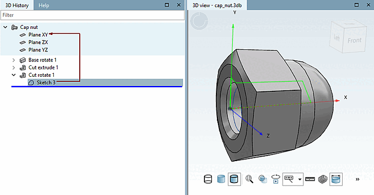
.In the context menu of Sketch 3, select: Section [Cut] -> Rotate.... [Rotate...]
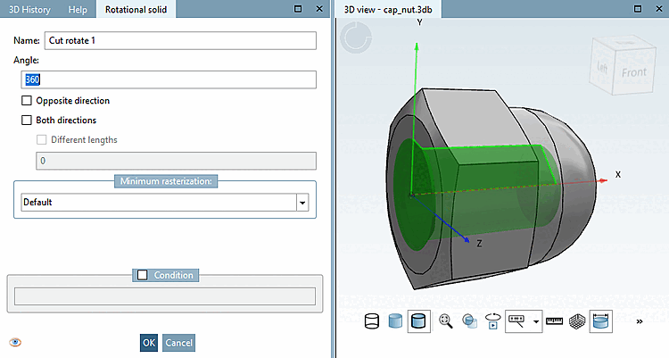
-> The docking window Rotating body [Rotational solid] is opened.
Leave the settings as they are and confirm with .
-> The completed cap nut is displayed in the 3D view.
-> If you are saving for the first time, the Identification details [Identification data] dialog box opens. Make the appropriate entries and confirm with . See above.
Close PARTdesigner and return to PARTproject back.
![[Note]](https://webapi.partcommunity.com/service/help/latest/pages/cn/partsolutions_user/doc/images/note.png)
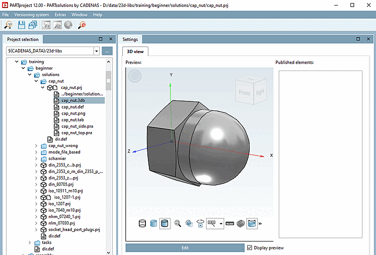
Note To make the geometry visible in the preview, select the corresponding 3db file in the Project selection dialog area.