 |
Drawings can be enhanced with BMG layers according to DIN 4003. When exporting 2D DXF/DWG these layers transfer important information for Tooling and BIM, among others.
Precondition: CNS classification with respective data
In PARTdesigner, in the docking window 3D History, click on the context menu command New 2D drawing....
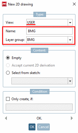
-> The dialog box 2D drawing is opened.
Under View, select the option User.
Under Name, for example, enter BMG.
Under Layer group, select the option BMG.
-> The Sketcher is opened. (The button group Text
 is visible for drawings.)
In the Sketcher, create your drawing as usual.
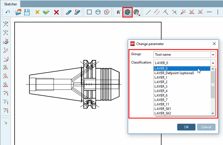
In order to classify drawing elements mark a line and click on the icon Classify element
 .
.In the dialog box Change parameter, select desired Group (here Tool name) and Classification (Layer).
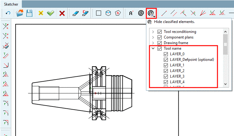
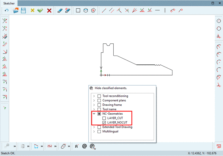
With Hide classified elements
 , you can hide or show all layers of a group or
single layer and check in the way, if everything has been set
correctly.
, you can hide or show all layers of a group or
single layer and check in the way, if everything has been set
correctly.-> The respective dialog area is opened.
Activate/deactivate the checkbox at desired groups or layers.
Currently all lines are displayed in black.
Line thickness can be thick or thin. Options for Line type are solid, dashed, dashed/dotted and double dashed/dotted.
Depending on layer, the lines are shown thick or thin. Detailed information on the single layers can be found in the specification DIN SPEC 69874-2.
In the Sketcher, finally click Accept changes.
-> The layer is shown in the 3D History.
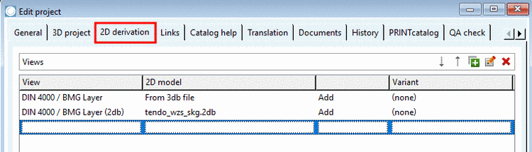
Under PARTproject -> Edit project -> tabbed page 2D derivation, determine that the 2D sketch is displayed.
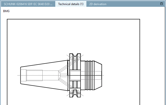
In PARTdataManager, the additional drawing is shown under Technical details .
![[Note]](https://webapi.partcommunity.com/service/help/latest/pages/cn/partsolutions_user/doc/images/note.png)