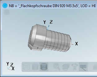
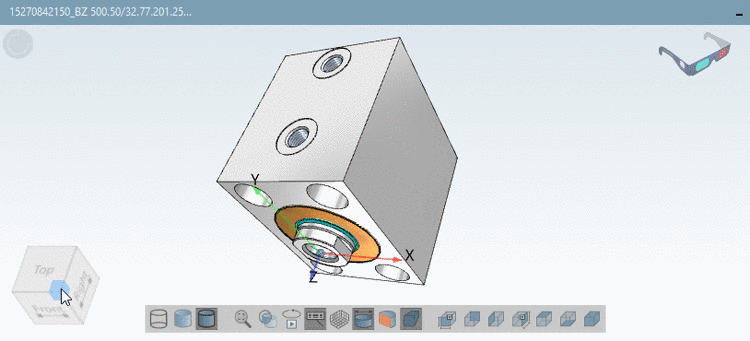
In the Display area you can make the following settings:
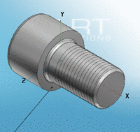
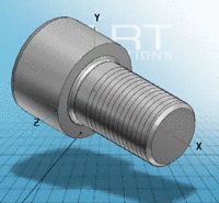
You can find the following selection options in the list field:
![[Note]](https://webapi.partcommunity.com/service/help/latest/pages/cn/partsolutions_user/doc/images/note.png)
Note The setting only describes the template during loading the part. You can change the display mode using the corresponding toolbars in the user interface.
Part color is based on the color of a single part in an assembly. This option only refers to assemblies with colorful parts.
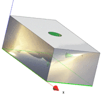
Display of the part in plastic 3D preview. The three dimensional effect only takes place when using red/cyan glasses!
To increase the effect of the plastic effect, the selected part is displayed flushed. The background is automatically darkened. The option red/cyan effect can be used independent of the display mode (Lines, Hidden lines, Shaded , etc.).
You can turn the option on/off per default via the checkbox.
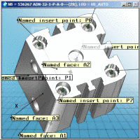
See also Section 5.12.9, “Create Published elements (classify connection points) ” in eCATALOGsolutions Manual.


