|
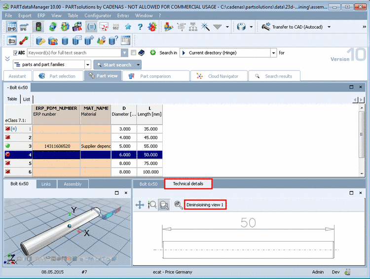
Dimensioning views displayed in PARTdataManager, in the dialog area Technical details (e.g. Side view, Front view, etc.) are available in PARTproject as *.pra files. Normally the dimensioning views are provided as DWG or DXF files by the customer.
As of V10.00 SP0 there is an importer / converter available in PARTproject for these files.
In the course of the import the layer are mapped on PRA pens. Complex forms such as text or arrows are automatically splitted into lines.
In the following the approach is shown with the help of a simple example:
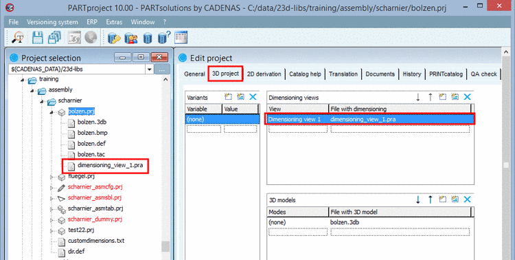
Select the tabbed page 3D project.
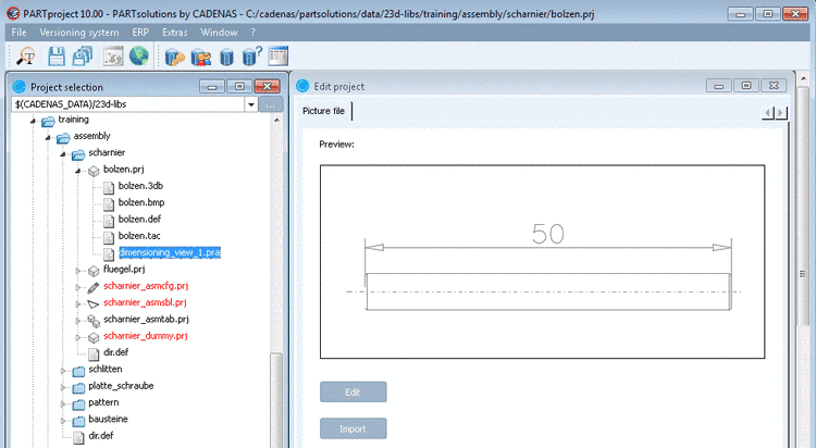
Add a new line under Dimensioning views. On the left side the name, which later shall be displayed in PARTdataManager and on the right side the desired file name for PARTproject.Confirm by clicking the Return key.
-> The file name is displayed on the left side in the Project selection.
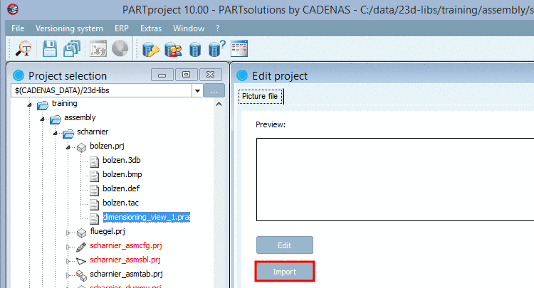
Select the file and click on .
Select the desired DXF/DWG file and confirm by clicking on .
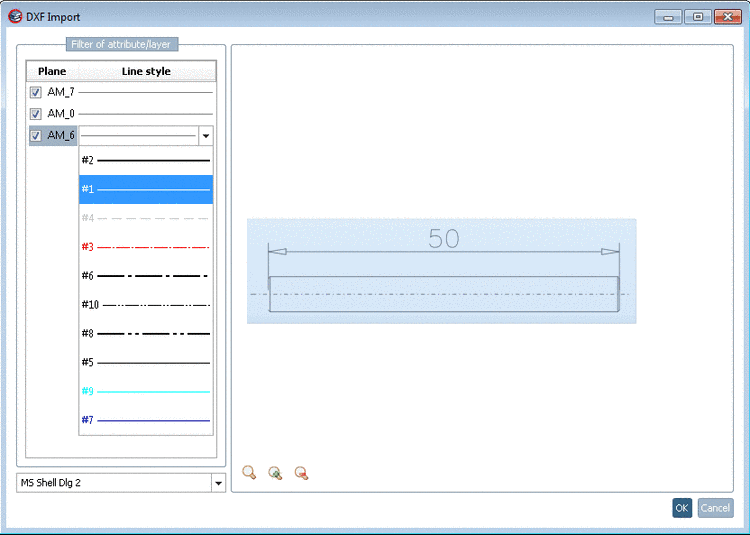
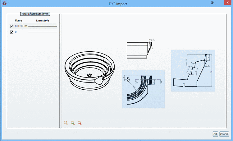
-> The dialog box "DXF import" appears with the chosen DXF view.
Under Plane, activate/deactivate planes (AutoCAD layer) via checkbox. Adjoining on the right side, under Line style, you can assign the desired PRA pen by opening the list field when clicking on a line.
Furthermore, when clicking on the respective button, you have the following functions available:
Zoom all
 , Enlarge
 und Reduce
 .
.Selection area (blue rectangle)
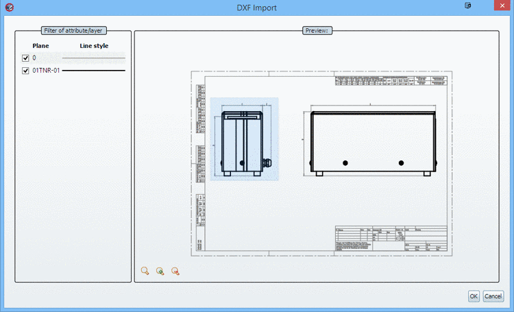
Draw up the blue rectangle anew as desired. The section marked by the blue rectangle is overtaken into the PRA file. In this way you can remove the frame from the DXF file or select a certain view.
You can perform a multiple selection with pressed Ctrl key.
-> A preview of the dimensioning view is displayed.
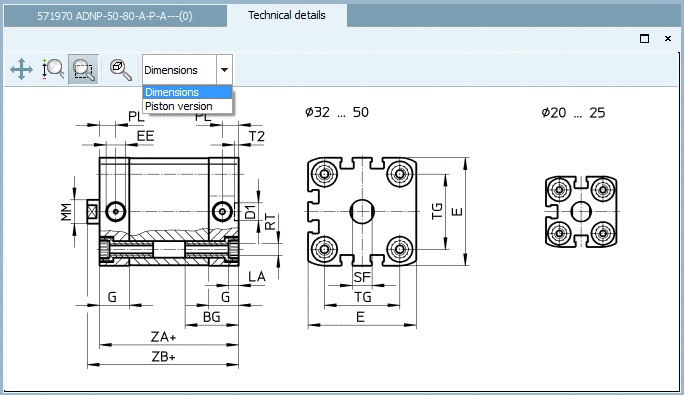
The dimensioning view is displayed in PARTdataManager, in the dialog area Technical details later. If multiple dimensioning views are available then you can select the desired one in a list field.