The following is a short version of a characteristic attribute table.[81]
Create a new project in PARTproject create a new project. You can find a small example of this at Section 5.5, “Create project - Small example from A to Z ”.
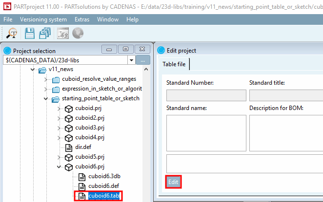
Select the *.tab or *.tac file in the project to be edited.
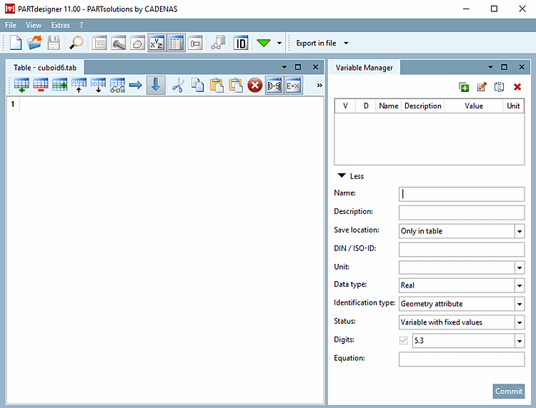
--> PARTdesigner is opened in the table view.
The Variable manager [Variable Manager] docking window is opened in the table view together with the Table docking window by default.
![[Note]](https://webapi.partcommunity.com/service/help/latest/pages/cn/3dfindit/doc/images/note.png)
Note If required, use the corresponding buttons on the standard toolbar [Default] or the menu items in the View menu [View] to show and hide individual docking windows.
Move the individual docking windows and adjust their size. A detailed description of the placement method can be found under Section 2.1.5.4, “Placing method for dockings ” in PARTsolutions - User
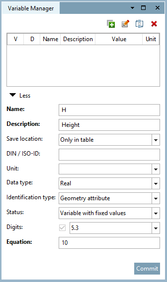
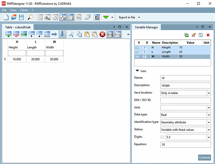
Create the variables L (Length), W (Width) and H (Height) for a cuboid in the variable manager [Variable Manager]. Details on the variable manager [Variable Manager] can be found at Section 7.8, “ Docking window " Variable manager" ”.
The Only in table option is already selected under Storage location [Save location], as PARTdesigner was opened via the tab file.
With this option, all input fields are active. Details on the individual parameters can be found at Section 7.8.10, “ Variable manager - The individual parameters ”.
For starters orient by the following figure.
--> Immediately after a variable has been created in the variable manager [Variable Manager], it is also displayed in the table.
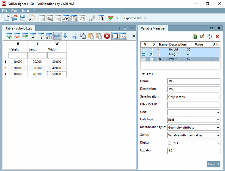
Add further characteristics to the table using Add row
 to add further characteristics to the table.
-> The Identification details [Identification data] dialog box opens with the Table tab. Fill in the mandatory fields Standard designation [Standard name], Parts list designation [Description for BOM], Standard number and Standard title. You can find details on this at Section 7.18.9, “ Identification data ”.
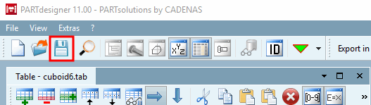
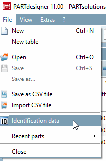
The dialog box can be opened at any time via File menu [File] -> Identification details [Identification data] or via
 to open the dialog box.
![Standard toolbar [Default]](https://webapi.partcommunity.com/service/help/latest/pages/cn/3dfindit/doc/resources/img/img_c3dca4cb1caa48f58d285540b6d34bb2.png)


![View menu [View]](https://webapi.partcommunity.com/service/help/latest/pages/cn/3dfindit/doc/resources/img/img_292e0cfe1e8644b3b29158c4609a001a.png)


!["Identification data [Identification data] " dialog box - "Table" [Table] tab page](https://webapi.partcommunity.com/service/help/latest/pages/cn/3dfindit/doc/resources/img/img_a88ae3192a654109b3890a4dced3ee63.png)
After finishing the table, in the next step the 3D model is created.
To do this, open the 3db file from PARTproject open the 3db file. The variables are automatically transferred from the linked tab/tac file (with the same name).
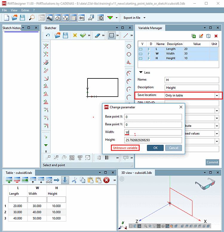
Select the option In geometry and table under Storage location [Save location] for all variables that are to be used in the sketch. You can find details on this at Section 7.8.11, “ Storage location: Only in geometry | Only in table | In geometry and table ”.[82]
Otherwise the error message Unknown variable [Unknown variable] is displayed.
Create the 3D model based on the created variables. A small example on this can be found under Section 7.4, “Create 3D model: Small example from A to Z ”.