Some parts have Value range variables. For these no fixed value is specified.
In the vertical
view these parts are marked by  :
:
| ||||
In order to specify the concrete characteristic, all value ranges have to be specified as well.
Depending on part specifications there are different ways of value range selection.
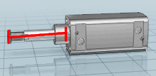
Changing the value immediately changes the display in the 3D view.
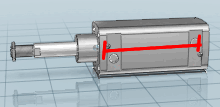
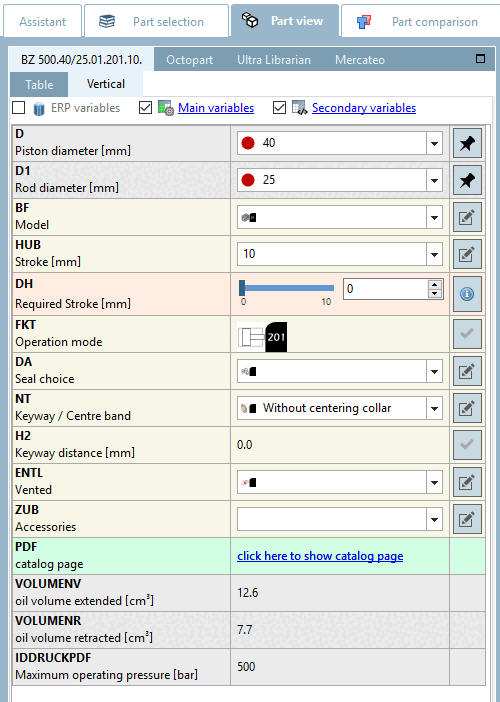
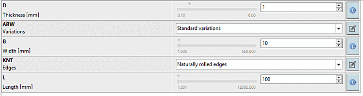
Value range: Enter a desired value within the value range or select the value using the slider.
The red line marks the default value. When clicking on it the default value is set again.
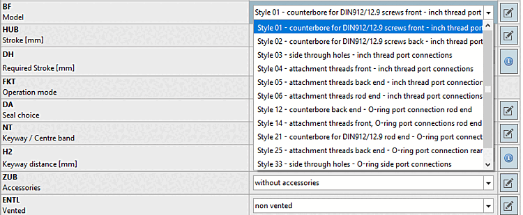
Selection of discrete values: Select the desired option from the list box.
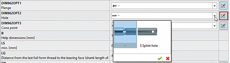
Selection of discrete values with preview images:
Graphics can also be displayed to clarify the selection options in value range fields. Select the desired option by double-clicking on it.
Meaning of colors for value range fields
![[Note]](https://webapi.partcommunity.com/service/help/latest/pages/cn/3dfindit/doc/images/note.png) | Note |
|---|---|
Colors must be activated. See above. | |
Depending on
pre-settings, colors are displayed in the symbol  , which point out different types of value
range fields.
, which point out different types of value
range fields.
 Yellow = geometric feature [Geometry attribute]
 Orange = functional feature [Function attribute]
The functional characteristic [Function attribute] is used for stroke and angular positions, everything that defines a mechanical movement in a part/assembly (e.g. the stroke position of a cylinder).
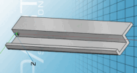
 Dark yellow = dimensional characteristic [Dimension attribute]
The dimensional characteristic [Dimension attribute] is used for semi-finished products and profiles that are produced in running meters.