The first solid with the plans XY / ZX and YZ has already been created.
Right-click on the name "Solid 1" to open the context menu. There you have various options, such as Rename, New instance operation, Set material, Insert absolute layer... [Insert Fixed plane...] or Delete.
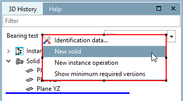
Right-click on the file name at the top (next to the view selection) to create a new solid.
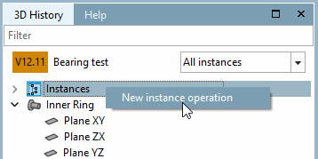
Right-click on instances [Instances] or on the name of a solid to create an instance via New instance operation. The default position for each newly added solid (so that you immediately get a visual representation of the solid) is a single instance without rotation in the center of the component.
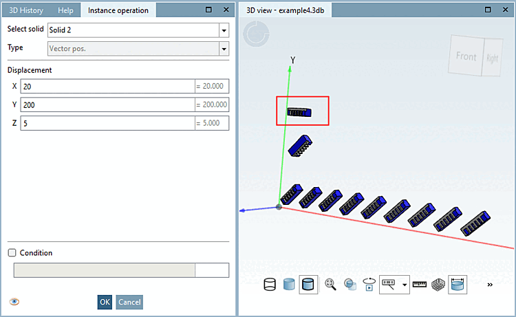
Select a type and enter at least the required fields.
The positioning of the instance is defined by the specified X, Y and Z coordinates. Rotation is not possible.
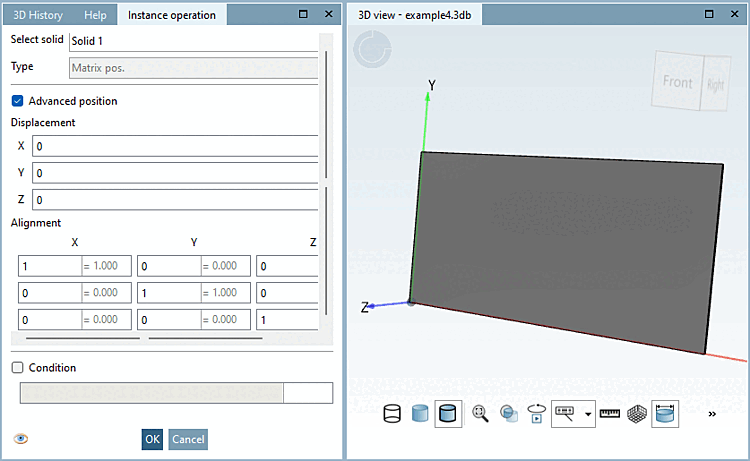
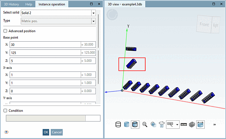
With Matrix pos. it is possible to place an instance with several parameters. The inputs are similar to those of an absolute plane, but an input in matrix style is also possible. This type of positioning enables both a shift and any rotation. For other instance operations such as linear or rotation patterns, this positioning is also included in order to define the starting position from which the pattern is to be started. These operations are therefore an extension of this.
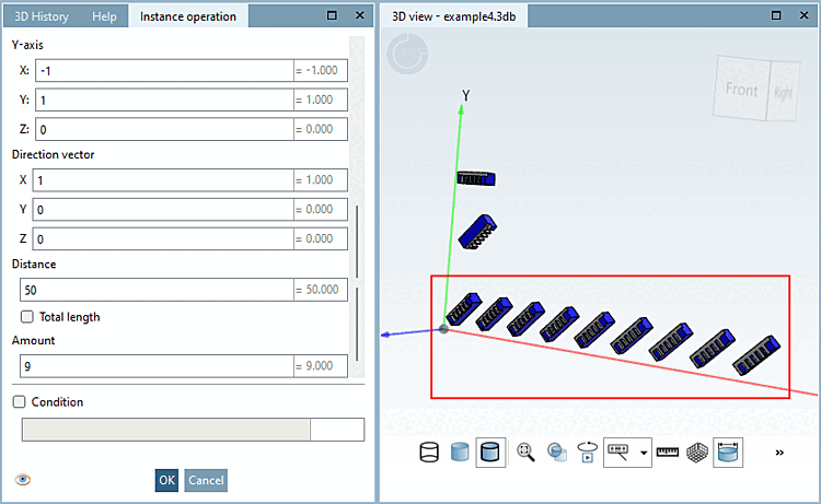
Create instances with linear repetitions. The linear pattern starts at a base position, which is defined as in the matrix pos. Starting from this base position, the pattern is defined by a direction in vector style. The pattern is precisely defined by the number of repetitions and either the distance between the individual instances or the total length.
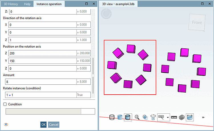
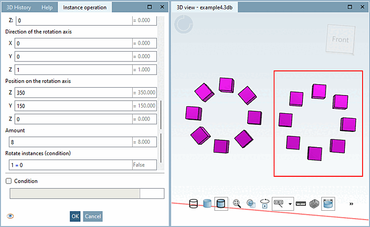
Create instances in a rotation pattern. The rotation pattern starts at an initial position, which is defined as for the matrix pos. In the next step, you define a rotation axis by a direction in vector style and a point on the axis. The rotation pattern is currently always a full circle, so the pattern is precisely defined by the number of repetitions. The "Rotate instances" field works like a condition that is either true or false. Depending on this, the instances are either rotated around the rotation axis itself or not.
Once all instances have been created, you have successfully created a Multi Solid single component. Make sure that you save your part before exiting the application.