5.12.11.13. ECAD assemblies - Control cabinets
5.12.11.13.1. Composition of the components (higher-order assemblies in 3D space) |  |
| Prev | Next |
Many ECAD systems (ECLASS Advanced, EPLAN, Zuken, E3) build assemblies with the help of special 3D classifications. These mechanisms represent a special subset of the possibilities offered by our Mate system. In particular, component assembly is achieved with the help of component holders and fastening variants.
In contrast to the usual CADENAS assemblies, such "extended" assemblies contain further classified connection points, i.e. component mounts and mounting variants. The fastening variant describes the orientation and position with which the given part is attached to a component holder of the parent part.
In general, there is a main part with several component recordings to which a number of smaller components are added. This results in hierarchical parent-child relationships, although the generality is restricted in contrast to our Mate system. For example, no "circles" can be plugged together, as a part cannot be both parent and child at the same time.
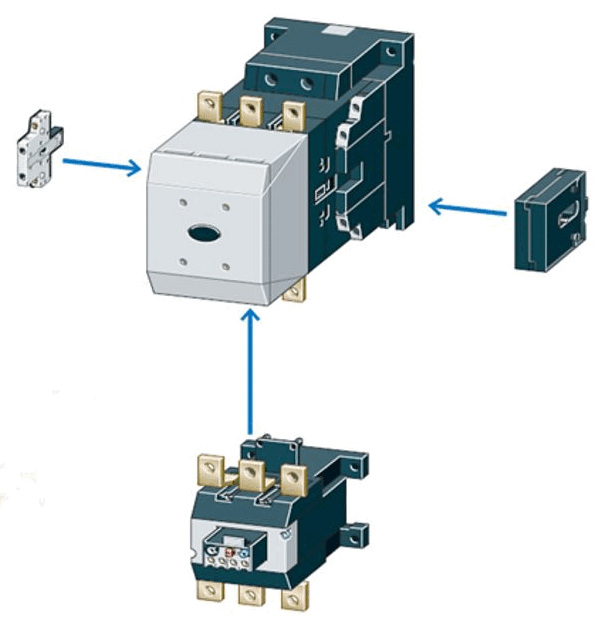
Circuit breaker: Attachment of additional devices. The additional devices cannot be additionally connected to each other (=> circuit).
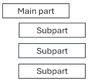
Plugging additional devices together leads to a hierarchy. The order of the subparts is irrelevant without further information.
In the ECAD area, we generally work with a special subset of the possibilities offered by our Mate system. During assembly, the corresponding coordinate systems of the underlying connection points are brought to congruence. Any flips of the coordinate axes are not provided for.
Note: The scheme described is a special ECAD feature that is particularly useful if the individual subparts are to be installed interactively in the corresponding ECAD system in new enclosure projects or are to be moved manually to other slots. CNS assemblies without these extensions can be used in ECAD systems without restriction, but in these cases they cannot be used in other engineering processes.
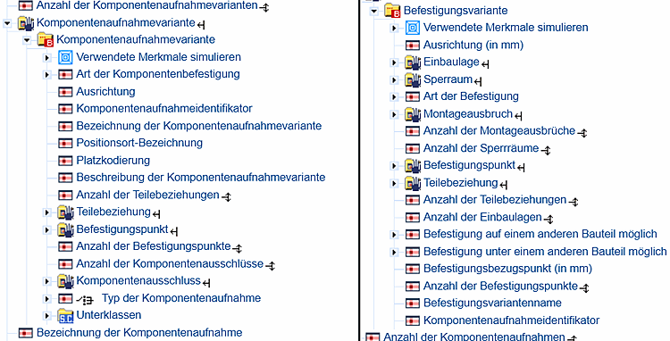
According to the ECLASS standard (from version 16), the compatibility of possible slots and fastening variants of the subparts is determined by identical identifiers. This means that the component mount (or more precisely the component mount variant) of the main part determines in its "component mount identifier" attribute which subparts can be plugged in using their mounting variant with the same attribute (also "component mount identifier"). This is mirrored by completely identical attributes in the CNS classification, where the following applies: Mounting variant = Mounting Description [CNS_CP|4|7] and component mounting variant = Mounting Point [CNS_CP|4|6].
Please note that only parts that actually have a 3-dimensional, finite volume can be combined using this method. A counter-example where this method is not applicable are semi-finished products such as cables or certain profiles where the length is not specified. Such parts do not have a fixed volume and therefore cannot be assigned the corresponding classifications.
In addition to the obvious advantages of this scheme, however, certain restrictions regarding fully automatic assembly must be taken into account:
A subpart can have several possible fastening variants with different orientations and positions, so that the ECAD system has to make a selection without any extra information. In interactive engineering, this is a user input. The first fastening variant is generally selected as the default.
In principle, such a 3D structure provides a definition of the sequence of the individual subparts. In the interactive modeling process, this is in turn determined by the user input.
Cases in which there are more possible slots than available subparts are problematic; here it is not specified which component slots are actually occupied.