
Assemblies have some special features compared to "normal" MCAD/CNS assemblies. This applies in particular to the fundamental property of the bill of material.
The following figures show a comparison of one and the same control cabinet in PSOL versus EPLAN and serve to illustrate the difference between these two engineering approaches (MCAD <-> ECAD).
In EPLAN, it is noticeable that there are far fewer components. While MCAD focuses on the mechanical-geometric properties, this abundance of components would basically be prohibitive for a meaningful engineering application when used in an ECAD system. There are two main challenges in modeling:
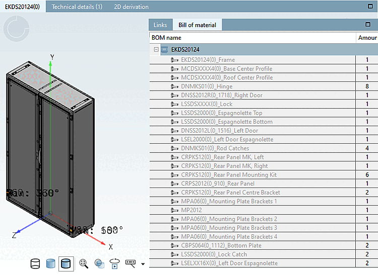
Typical control cabinet including BOM in the CADENAS view. Note the large number of components resulting from the MCAD focus, where special emphasis is placed on the geometry.
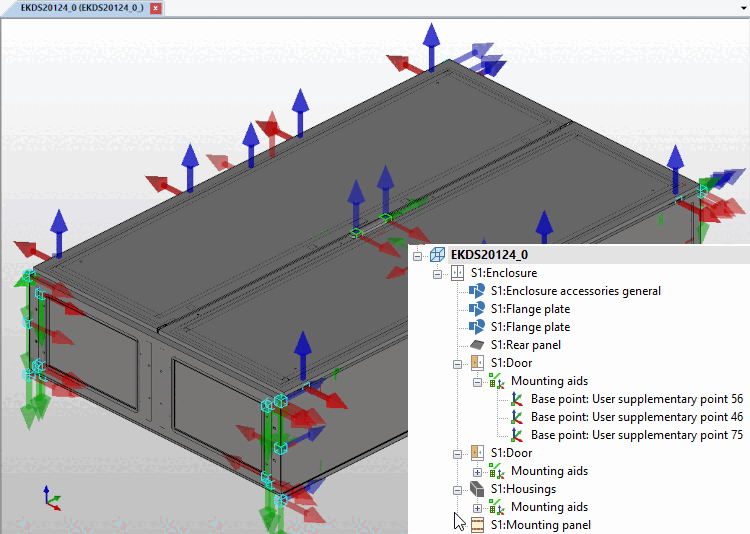
The same control cabinet from above in a typical ECAD system (here EPLAN). Note the lower number of components in the BOM resulting from the functional ECAD requirements.
In the following illustration of a component of the control cabinet, the different requirements and special features of typical ECAD systems are made clear. The associated component was dynamically generated from a large number of individual CADENAS parts during export and must be understood as a "virtual" accessory/part. This serves to illustrate the different approaches of MCAD compared to ECAD. Overall, the same geometries / solids are described in both systems, although a completely different engineering approach is followed.
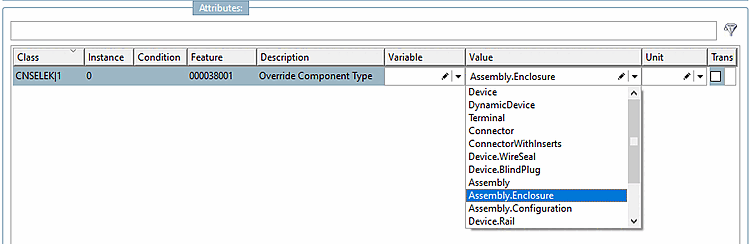
In principle, it cannot be determined a priori and above all automatically that the given CADENAS assembly is an individual part or an assembly for the ECAD view. For this reason, this information must be explicitly specified at the assembly level via a corresponding classification. The class CNSELEK|5|1 or the attribute 000038001 (with value list) is used for this by setting it to the predefined values "Assembly", "Assembly.Configuration" or "Assembly.Enclosure". This enables the subsequent systems to explicitly interpret the current CADENAS assembly. This situation is shown in the following image.
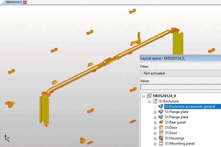
The figure illustrates the effect of the first point in the above list, in which the abundance of components is greatly reduced. The geometry shown includes more than 40 components from the CADENAS project.
The situation described above leads to a whole series of difficulties and possible inconsistencies. This results in very special requirements for the classification system and the filling with corresponding data, which are ideally already taken into account during geometric modeling.
In terms of standardization, ECLASS-Advanced already has an elaborated system with the aspect "Composition of components" (AGZ169), which serves as the basis for our classification system. This classification (which "lives" on the assembly) lists all components / instances of the assembly and describes the part relationships, i.e. the part relationships between suitable pairs and components that are assembled with each other in three-dimensional space via source and target mates. As a rule, source and target mates are described by mounting descriptions and component mounts/mounting points. Each component of the assembly instantiates a "Component" block.
This structure basically fulfills all of our requirements listed above. There are already predefined mates in the CNS system for assembling an assembly, so that we can limit ourselves to the description of the individual components (without 3D). The creation of "artificial" / composite components shown as an example in the image above can also be accomplished very easily with the following classification.
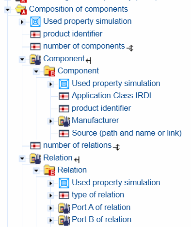
The data model in ECLASS-Advanced for describing the structure of an assembly consisting of individual (but complete) items
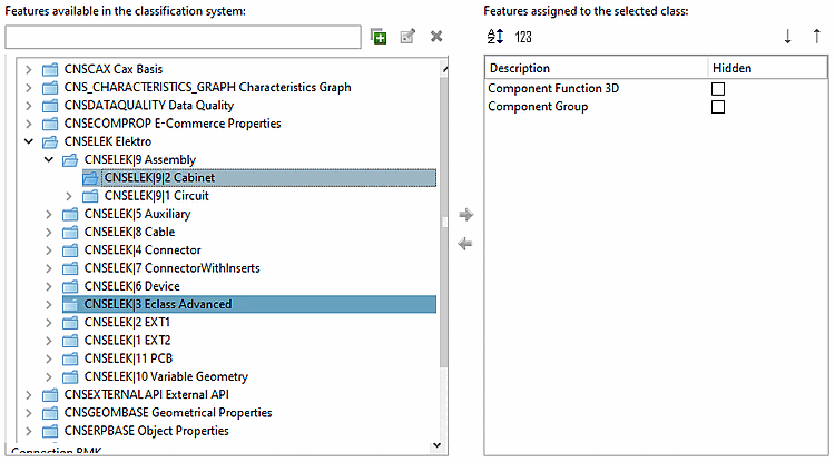
The Component Group attribute allows the MCAD assembly structure to be summarized in individual groups according to ECAD.
The attribute Component Function 3D assigns certain mechanical functionalities such as door, lock, etc. to the corresponding groups. At present, only a few ECAD systems, in particular EPLAN, can process this information. This attribute is numbered, the permitted values are given by the following values:
Door
Door left
Door right
...
...
Panel general
Side panel left
Side panel right
In this way, the mechanical functionality of the individual components ("component groups") is specified more precisely in the control cabinet context.
In an MCAD assembly, each component is given an instance of the class CNSELEK|9|2 (Cabinet Classification). The processing codes (interfaces, translators) merge all components with the same value of the Component-Group attribute into artificial, unified geometries (see figure above ). We emphasize that this process is only possible with special, very simple components, which in a way act as filler.
Syntax for filling component groups:
Identifying string + @ + optional numeric value such as "Accessories@3".
In this way, 1. the abundance of components in the CNS system can be greatly reduced, and 2. it is possible to directly influence the sorting of the resulting artificial components in the ECAD system. Thus, all components were labeled with the component group "Enclosure accessories general@1" (see figure above ), so that it was ensured that the combined component (see figure above ) appears first in the EPLAN BOM list.
As a rule, only the geometry is combined for combined parts; the individual components then contain no CP classifications or information such as CNSORDERNO, for example. Note: As soon as two of these components are combined, each of which has an article number defined, a conflict arises in such a way that the combined part can no longer have a well-defined article number. In this way, the described process can only be carried out under certain conditions:
The "leading part" provides information such as CNSORDERNO, which is valid for the entire combined part.
The additional parts are modeled in such a way that they only contain "compatible" classifications; these are in particular mounting points, drilling patterns, fastening variants/mounting descriptions, blocking spaces, etc. Electrical connections and, in particular, any information from the ERPBASE and information such as different ECLASS numbers are problematic.
These prerequisites result in a scheme of purely geometric summarization which, with appropriate modeling, enables mapping of the CNS assembly structure to the ECAD engineering approach.

The functionality of the "Cabinet" classification for an individual component is shown as an example in the image above. In the case of real component groups, identical classification information must be assigned to the associated parts. As the CNS_COMPONENT_GROUP attribute is assigned the run index "@1", it appears at the top of the component tree in EPLAN, for example.