5.12.11.28. Classify
electrical parts: Additional modules 5.12.11.28.1.
Connectionpoint
Wizard
|  |
| Prev | Next |
![[Note]](https://webapi.partcommunity.com/service/help/latest/pages/cn/3dfindit/doc/images/note.png) | Note |
|---|---|
The prerequisite for using the module and displaying the context menu command is that the files | |
| Note |
|---|---|
The connection point wizard [Connection point wizard] is ideal for use with the Electrical classification import/export plugin. | |
With the
Connection Points Wizard [Connection point wizard], you can use
of the functions  create Cp (Ctrl+C) [Create Cp (Ctrl+C)]
(for a single feature),
create Cp (Ctrl+C) [Create Cp (Ctrl+C)]
(for a single feature),  Generate Cp (All)
(Ctrl+A) [Create Cp (All) (Ctrl+A)] (for all identical features) or
Generate Cp (All)
(Ctrl+A) [Create Cp (All) (Ctrl+A)] (for all identical features) or  Save as template
(Ctrl+S) [Save as template (Ctrl+S)] automatically set attachment points to features.
Save as template
(Ctrl+S) [Save as template (Ctrl+S)] automatically set attachment points to features.
You also have the option of using the functions  Create BoundingBox Cp (Ctrl+B) and
  Save BBox as template to place a connection point at a corner of the BoundingBox. See also Section 5.12.11.1, “Align
component”.
Save BBox as template to place a connection point at a corner of the BoundingBox. See also Section 5.12.11.1, “Align
component”.
In the following, first the basic setting options will be explained. Then two examples follow, one to explain setting of connection points on features, one on the BoundingBox.
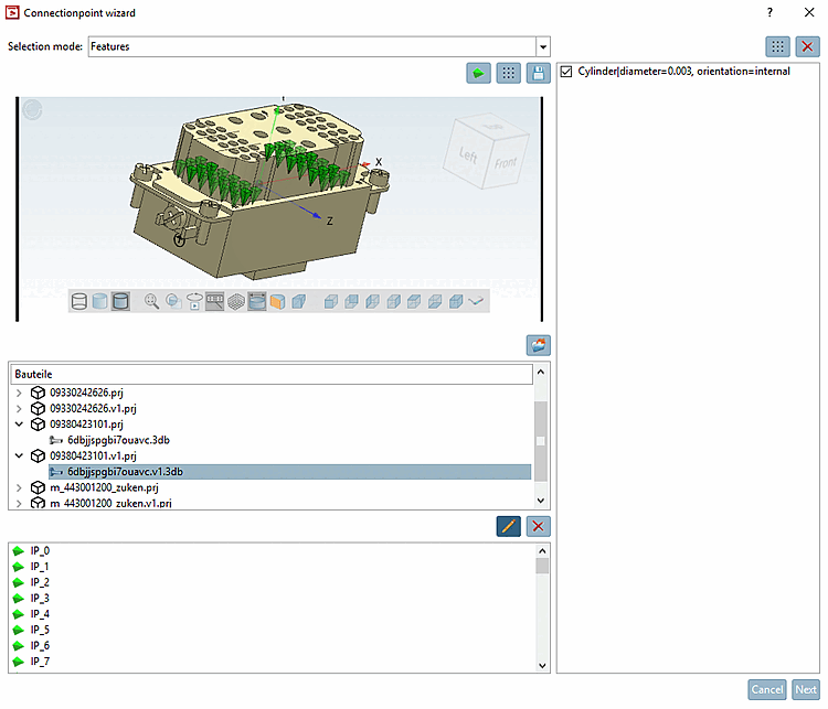
Select the desired directory level in the index tree. The projects directly below are then displayed in the Components [Parts] dialog area, which are then available for editing.
Call up the connection points wizard [Connection point wizard] in PARTproject under Project selection -> Context menu of the directory -> Automation.
Select the 3db file of the desired part.
Select one of the following settings under Selection mode:
None: If no 3D selection is required. You can select this option if you want to place connection points at corners of the bounding box (the other options are also possible for this)
See below.
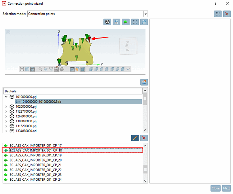
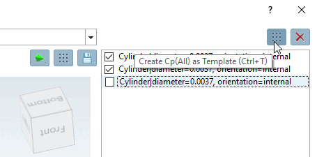
Connection points [Connection points]: Select this option if you want to determine the name of a connection point. When selected in the 3D view, the point is highlighted at the bottom of the list.
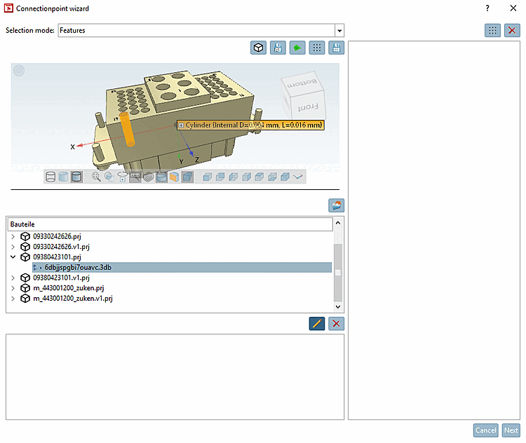
Features: Select this option if you want to automatically add connection points to features, either individually or for all identical features.
See below.
To select one of the functions
Create BoundingBox Cp (Ctrl+B) or
Save BBox as template, no special option must be selected under Selection mode.-
Create BoundingBox Cp (Ctrl+B)
With the help of this function you can create a connection point on a corner of the BoundingBox.
See below.
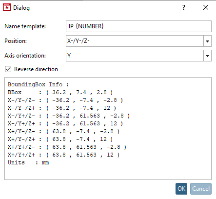
When clicking on the icon the respective dialog is opened.
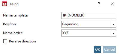
Set the desired entry under Name template, Position, Axis alignment [Axis orientation] and Reverse direction and confirm with .
-> The connection point is placed on the desired corner of the BoundingBox.
After clicking on the button, the same dialog box opens as under Create BoundingBox Cp (Ctrl+B).
Select the desired settings and confirm with .
-> The template is saved and displayed in the dialog area on the right side.
By clicking on
Create Cp(All) from templates (Ctrl+T) [Create Cp(All) from Template (Ctrl+T)] at the top right, you can set the corresponding connection point on the bounding box from the activated template.
To select one of the features
Create Cp ( Ctrl+C) [Create Cp (Ctrl+C)] (for a single feature),
Create Cp (All) (Ctrl+A) [Create Cp (All) (Ctrl+A)] (for all identical features) or
Save as template (Ctrl+S), the Features option must be selected under Selection mode and a feature must be selected in the 3D view.Otherwise an error message is displayed.
-
Create Cp (Ctrl+C): An append point is set on the selected element.
-
Create Cp (All) (Ctrl+A): An append point is set specifically for the selected element and also for all identical features.
-
Save as template (Ctrl+S): You can use this function to create and save templates. To do this, select a feature and then click on the icon.
-> On the right side a template is displayed.
Click on
Create Cp (All) from templates (Ctrl+T) [Create Cp(All) from Template (Ctrl+T)] in the top right-hand corner, you can create connection points from the activated templates.
![Connection points wizard [Connection point wizard] - Call](https://webapi.partcommunity.com/service/help/latest/pages/cn/3dfindit/doc/resources/img/img_c113526ff0d9404081dcc0522ce726e4.png)


![Error message: "Please select a feature [Please select a feature] "](https://webapi.partcommunity.com/service/help/latest/pages/cn/3dfindit/doc/resources/img/img_6349aced2b434424b4059b7bc62bad34.png)
Click on the button
Create BoundingBox Cp (Ctrl+B).-> The respective dialog box is opened.
Set the desired settings for the Name template, Position, Axis alignment [Axis orientation] and Reverse direction parameters and confirm with .
-> The connection point is set on the desired corner of the BoundingBox.
After clicking on one of the functions
Generate Cp
(Ctrl+C), [Create Cp (Ctrl+C)]
Create Cp (All)
(Ctrl+A) [Create Cp (All) (Ctrl+A)] or
Save as template
(Ctrl+S) [Save as template (Ctrl+S)] a dialog box opens to determine the
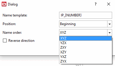
Parameter Name Template [Name template],
Reverse position [Position], name order [Name order], and direction [Reverse direction].
In the following, the procedure according to Using the Generate Cp function
(All)
(Ctrl+A) [Create Cp (All) (Ctrl+A)] shown.
Name template: Accept the suggestion or adapt the printout accordingly.
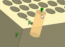
IP_{NUMBER} <default>IP_GROUP1_{NUMBER}Position: Choose between start, end or middle. With a cylinder, you can clearly see what is meant.
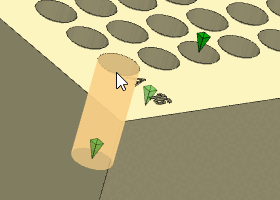
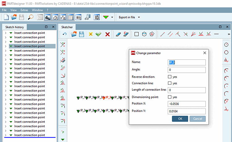
Name sequence [Name order]: Defines the type of numbering. It is carried out according to the priority of the 3D coordinates.
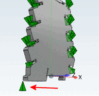
In the following exemplary figure the numeration is according to "XYZ".
Y doesn't matter, because all points have the same value for Y. The start point "IP_0" has the highest X and Y value. The second point has a X value of the same value, however, a lower Z value, etc. In the second row points with next higher X value follow, beginning with the highest Z value, etc.
Reverse direction: ... reverses the direction of the connection point.
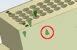
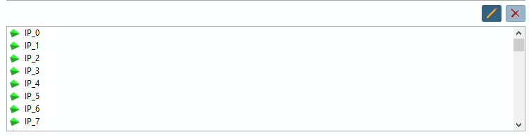
The following illustration shows the status after using the Create Cp (All) [Create Cp (All) (Ctrl+A)] function (Ctrl+A) [Create Cp (All) (Ctrl+A)]
.In the dialog area on the very bottom, all created connection points are displayed.
After clicking
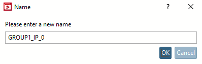
 , you can rename a connection point.
When clicking on
 , the selected connection point is deleted.
![Name sequence [Name order] -> Result](https://webapi.partcommunity.com/service/help/latest/pages/cn/3dfindit/doc/resources/img/img_a7b9dd33fc1a48dd95f7c8b9204de66f.png)
![[Tip]](https://webapi.partcommunity.com/service/help/latest/pages/cn/3dfindit/doc/images/tip.png)
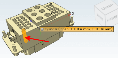
The function is required, for example, if placement points with the Z-axis of the connection point are to point into the ground and a cylinder in the X-direction is used as the origin of the point or if, for example, the connection point is not to be placed on the connection end for pipe connections, but offset inwards.
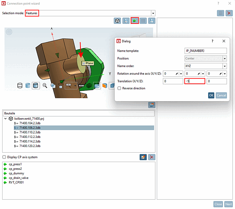
Select the part to be edited and call up the connection points wizard [Connection point wizard].
Under Selection mode, select the Features option and select a feature (in this example, a level).
Click on the button
Create Cp
(Ctrl+C). [Create Cp (Ctrl+C)]
-> The corresponding dialog opens.
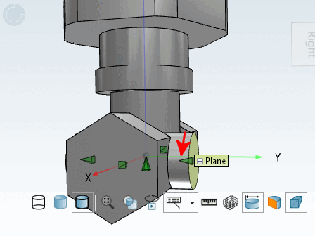
For example, select Translation = '-5' for the Y-axisand confirm with .
-> The connection point is set. It is offset inwards from the selected level.