5.12.11.5.2. Connections, IEC function symbols
5.12.11.5.2.1. Connections, functions, IEC symbols in ECLASS |  |
| Prev | Next |
As the concept described above has its origins in ECLASS Advanced, the relationships will be explained in detail here using the same component. In particular, connection definitions in the ECLASS Advanced format will also be discussed.
The following illustration shows the connection definition in ECLASS Advanced.
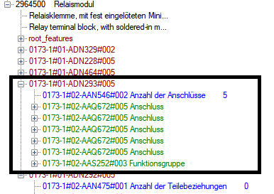
The device has 5 connections and 1 function group (see figure above). The function group is the container for the electrical functionality of the part and contains 2 functions in the given example.
According to this division 3D data and other properties of connections are defined in the sections AAQ672 (="Connection").
Information on connection logic, etc. are determined by the functions in the function group.
![[Note]](https://webapi.partcommunity.com/service/help/latest/pages/cn/3dfindit/doc/images/note.png) | Note |
|---|---|
Physical and logical connection properties are separated. This strict separation is not so strong in the CNS classification system. | |
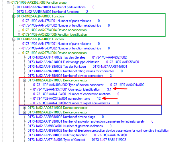
The most important information of a representative connection for part 2964500 is shown in the figure. In addition to its 3D coordinates with connection direction (see framed data in the following figure), AAQ672 usually also contains information on the conductor material, cross-sections, its color and stripping lengths, etc. (In this case, classification was only carried out sparingly without this additional information)
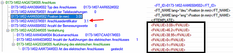
Properties of connection: The key AAM650 defines connection position and direction according to ISO AXIS ID data type definition. The relation to logical connection properties is realized by connection identifier AAN337 (here ID = 3:1).
The connection identifier links physical and logical connection properties.[53]
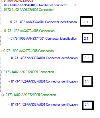
Connection identifiers of the five connections. All other data is hidden. (Above figure is representative for the other connection details omitted here).
In this case the five connections are divided in two functions (see "Number of functions 2"):
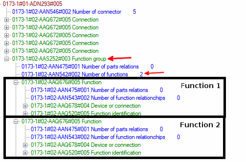
Function group with two functions (expands on the first level). Note that ECLASS is largely language-independent (English function and German function are both described by "AAQ676")
The link between connection and function takes place within the ECLASS key AAQ678. Two connections belong to the first function and three connections to the second function. As an example, we look at the corresponding function entry for identifier "3:1" in the illustration.
Function group with two functions. Two connections (within AAQ678; not displayed here) belong to the first function (green frame). The second function contains three connections (red and blue box). The entries of identifier "3:1" are expanded in the red box. Note the large amount of date, which serves the "bookkeeping" to a great extent.
The previous considerations can be summarized as follows: (You can see the function number indirectly in the figure above)
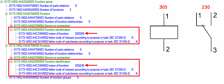
Now that logical connections are linked to the physical connections, the question arises as to what the corresponding switching symbol of the entire device (a device with one function group and two functions) looks like. This is done within the ECLASS key AAQ520.
The component is therefore described from the combination of S00305 (="coil") and S00230 (=switch).
In summary:
| Connection ID | Function number | IEC symbol | Connection EclassSymbolMap | |
| 4.1 | 1 | S00305 | A1 | S00305||1||1 |
| 5.1 | 1 | S00305 | A2 | S00305||1||2 |
| 3.1 | 2 | S00230 | 12 | S00230||2||1 |
| 1.1 | 2 | S00230 | 14 | S00230||2||2 |
| 2.1 | 2 | S00230 | 11 | S00230||2||3 |
On the CNS classification side, the Connection EclassSymbolMap feature shows a fairly compact formulation of the concept described.
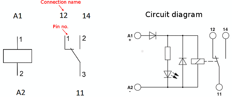
Following figure shows the comparison of the logic from the table with the circuit from the datasheet.