After you have clicked on in 3Dfindit or on in PARTdataManager, the view changes to CoCreate Modeling and the 3Dfindit placement dialog opens.
Select the desired placement method under 1. Select method using one of the following buttons:
If the Repeat [Repeating] checkbox is selected, the placement is automatically repeated until the user clicks . The next placement is started after the user has confirmed in CAD.
→ After you have selected a placement method, the CoCreate Modeling placement dialog opens.
If there are several insertion positions, the dialog changes first and "Select 2nd insertion position [2. Select insert position] " appears.
Select the desired insertion position from the list.
→ The CoCreate Modeling placement dialog opens.
It is not necessary to click on for the first placement.
Once the first placement has been completed, the component can be inserted again using . If the Repeat [Repeating] checkbox is selected, placement is automatically repeated until the user clicks . The next placement is started after the user has confirmed in CAD.
While the user has to interact in CAD, the 3Dfindit placement dialog is disabled to allow clear user guidance.
If you cancel or finish the placement procedure the dialog is activated again.
After starting the CoCreate Modeling placement procedure: If the desired part is not available in the opened model yet, it is tried to load the part from ModelManager - if active - or from the pool - if set. This may last a moment.

![[Note]](https://webapi.partcommunity.com/service/help/latest/pages/cn/3dfindit/doc/images/note.png)
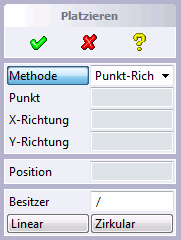
![1. Select procedure [1. Select method]: before selection](https://webapi.partcommunity.com/service/help/latest/pages/cn/3dfindit/doc/resources/img/img_578403a5d0924bdfaab63899ded2c602.png)
![1. Select procedure [1. Select method]: after selection with "Repeat" checkbox](https://webapi.partcommunity.com/service/help/latest/pages/cn/3dfindit/doc/resources/img/img_e094177571d94bfca88373b0b0e6d5e5.png)
In the following the procedure of the individual placement methods is explained:
There are two different placement methods available, which you can select from the list box:
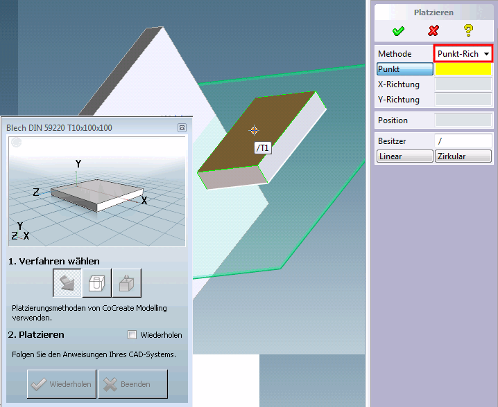
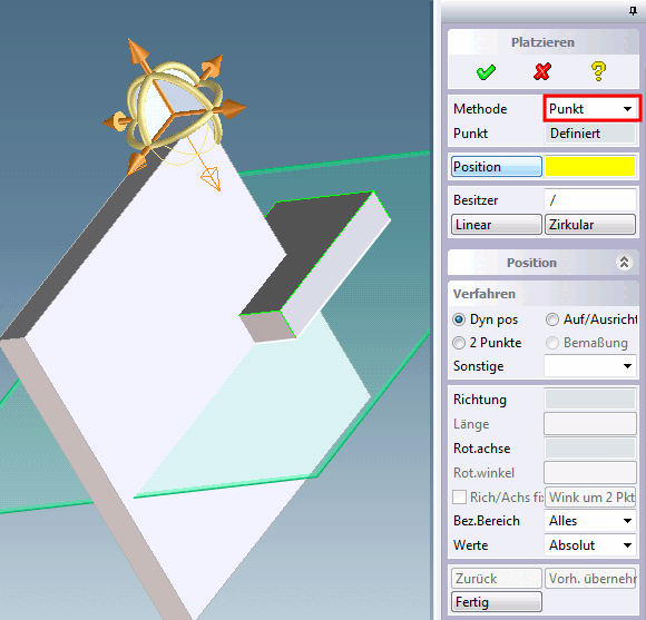
You have exported a 3Dfindit component to CAD and would now like to place it using the point-direction method.
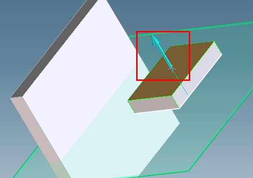
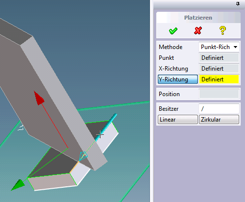
Now determine the X direction.
→ The component is placed in the desired position.
Click on and select the desired axis.
→ The component is now defined in the X and Y directions.
By clicking on , you can optionally place the component further using the CAD methods.
Determine the insertion point as described above.
By clicking on , you can optionally place the component further using the CAD methods.
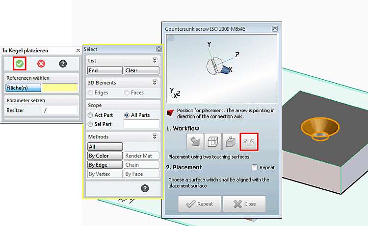
Owner: You can use the owner to select an alternative assembly into which the component is to be inserted. This step is only executed after confirmation with
 or after pressing the or buttons.
| : The or buttons are used to successfully complete the placement and start the creation of a pattern.
These dialog fields are a CoCreate internal function.
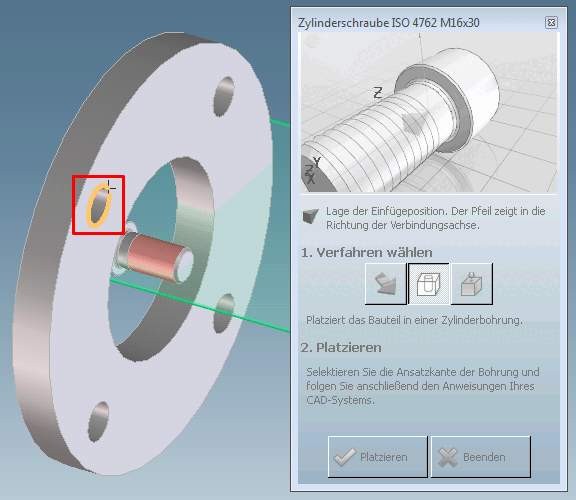
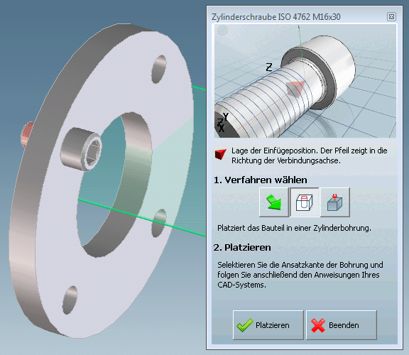
3Dfindit Placement Dialog In Cylinder Bore [In Cylinder]

At this place there are two variants:
The part to insert has several possible insertion points.
In this case the enhanced dialog is displayed.
Select the insertion position [Insertion position] from the list.
→ The 3Dfindit placement dialog is deactivated.
The further procedure is identically with the described in the following point.
The part to insert has only one insertion point.
The 3Dfindit placement dialog is deactivated.
→ The exported component is initially inserted into the assembly without being placed.
The Place in hole dialog opens in CoCreate.
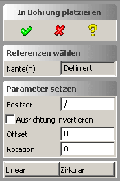
→ The "Defined" entry appears under Edge(s).
→ The component is inserted at the insertion point placed. (Preview: You can use
 cancel.)
You can use the owner to select an alternative assembly into which the component is to be inserted. This step is only executed after confirmation with
or after pressing the or buttons.You can use Invert orientation to change the orientation of the component (rotation by 180° around the X axis of the component). The view is updated.
You can use Offset to offset the component orthogonally to the plane through the selected circle edges. The value is identical for all edges. The view is updated after input.
You can rotate the component around the circular axis using rotation. The value is identical for all edges. The view is updated after input.
Use the or buttons to successfully complete the placement and start the creation of a pattern.
The dialog fields are a CoCreate internal function.
The and buttons are only available when selecting a single edge.
After the first placement with a method, the button becomes the button. You can place the component as often as you like.
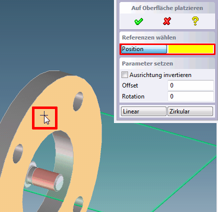
3Dfindit placement dialog on surface [On surface]
 .
.
At this place there are two variants possible:
The part to insert has several insertion points:
In this case the enhanced dialog is displayed.
Select the insertion position [Insertion position] from the list.
→ The 3Dfindit placement dialog is deactivated.
The further procedure is identically with the one described in the following point.
The part to insert has only one insertion point.
The 3Dfindit placement dialog is deactivated.
→ The exported component is initially inserted into the assembly without being placed.
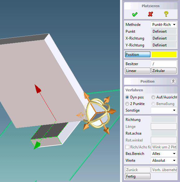
The Place on surface dialog opens in CoCreate Modeling.
On the desired plane click on the desired insertion point.
→ The entry "Defined" appears under Position.
→ The component is inserted at the insertion point placed. (Preview: You can use
cancel.)In the CoCreate dialog there are further setting options in addition:
You can use the owner to select an alternative assembly into which the component is to be inserted.
This step is only executed after confirmation using
or after pressing the or buttons.You can use Invert orientation to change the orientation of the component (rotation by 180° around the X axis of the component). The view is updated.
You can offset the component orthogonally to the plane using Offset. The view is updated after input.
You can use rotation to rotate the component around the surface normal through the selected point. The view is updated after input.
The or buttons are used to successfully complete the placement and start the creation of a pattern. These dialog boxes are an internal CoCreate function.
After the first placement with a method, the button becomes the button. You can place the component as often as you like.
3Dfindit Placement Dialog Touching Faces [Touching Surfaces]
 .
.
The Touching surfaces [Touching Surfaces] button is displayed for components classified accordingly.
→ The Place in cone dialog box opens.