
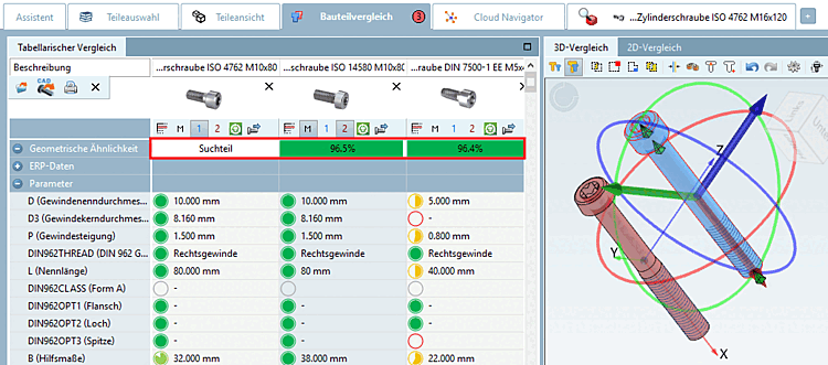
The tabular comparison [Tabular Compare] shows information on ERP data, data from the characteristic attribute table, topological information and classification data.
![Dialog area "Tabular comparison [Tabular Compare] "](https://webapi.partcommunity.com/service/help/latest/pages/cn/3dfindit/doc/resources/img/img_c88b85cd0e9544adb53a76f2581eeb13.png)
Geometric similarity [Geometrical similarity] (if a geometric search (3D) [Geometric search (3D)] was previously carried out)
Topology (the properties relevant for the comparison parts are displayed in each case)
![[Note]](https://webapi.partcommunity.com/service/help/latest/pages/cn/3dfindit/doc/images/note.png)
Note The quality of the topology information/features depends on various factors. See below for more information.
Classification data (all installed classifications are displayed)
The pie charts reflect the percentage similarity of the values.
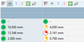
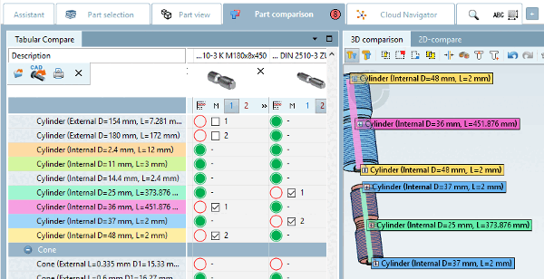
Colored marking of the topological parameters searched for
Topological parameters are color-marked so that you can see the most important ones at a glance.
![Topological parameters in the "component comparison [Part comparison] "](https://webapi.partcommunity.com/service/help/latest/pages/cn/3dfindit/doc/resources/img/img_76e16982e7844fd0b2300e5d6e40d994.png)
Explicitly searched topological attributes are marked in color.
The topological features that can be selected in the 3D view (e.g. circular pattern [Circular Pattern], inner cylinder [Inner Cylinders], outer cylinder [Outer Cylinders] ) are shown in the list under Tabular comparison [Tabular Compare] with a checkbox.
If you activate a checkbox, the corresponding parameter is highlighted in color under Tabular comparison [Tabular Compare] and in the 3D comparison. Different features are given different colors (regardless of whether they were selected automatically or manually).
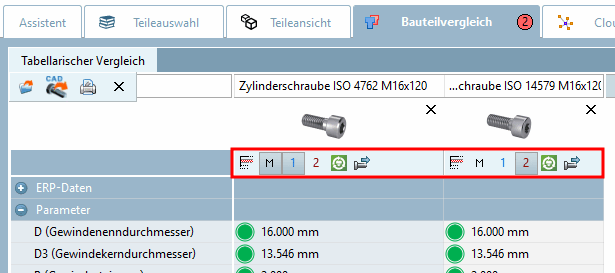
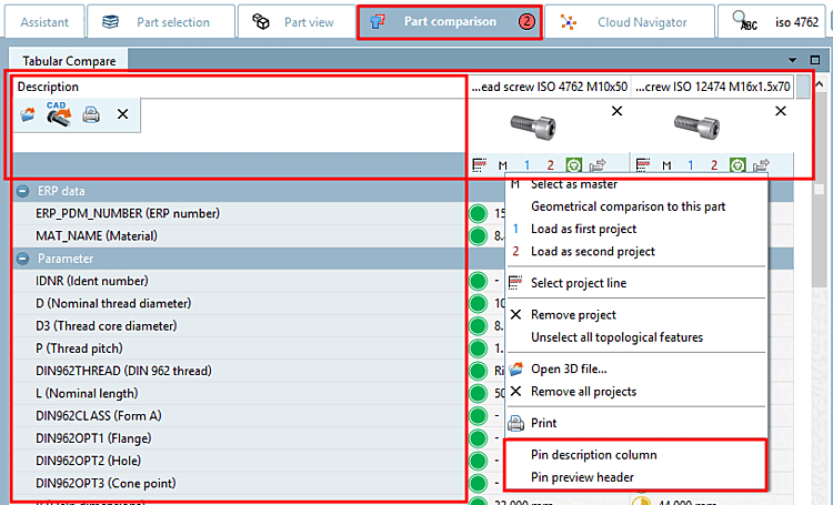
You will find the following icons in the column header:


For parts that are found via Geometric search (3D) and transferred to the part comparison [Part comparison], the geometric similarity is also transferred and displayed in the Tabular comparison [Tabular Compare] dialog area.[75]
Call: Right-click anywhere in the desired column.
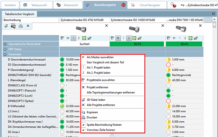
The following commands are available in the context menu:
Select as master [see icon above
 ]
]
The relevant column is displayed with a green background color
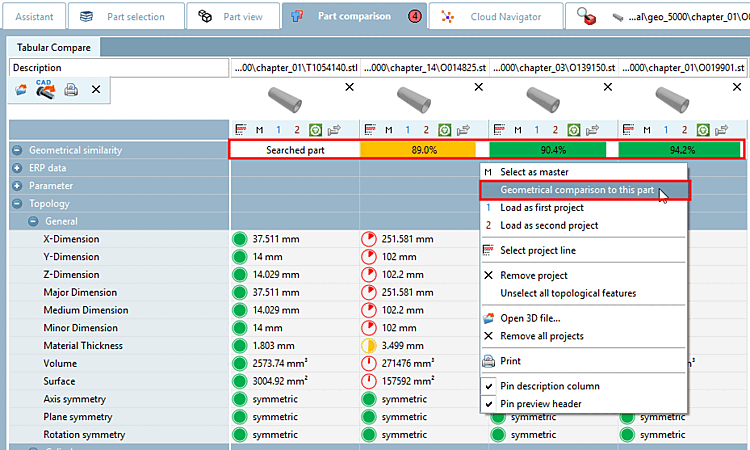
Geo-comparison [Geometrical comparison to this part] with this part:
Initial situation: Displayed percentages of geometrical similarity can be calculated by processes executed before or they haven't been calculated yet.
Regardless of this, you can recalculate these for each part in the component comparison.
To do this, call up the context menu command Geo comparison with this part [Geometrical comparison to this part] on the desired part. The search part (100%) is marked as such.
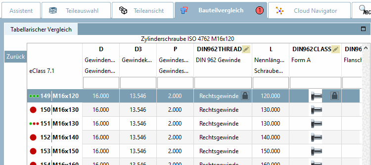
Select project line [compare aboveicon
 ]
]
Switches to the line view (see following figure)
Click on to return to the initial state.
For a meaningful 3D comparison, change the characteristic here so that the comparison parts have approximately the same dimension.
Unselect all topological features
(Markings are set according to the used search parameters.)
-> The colored markers in the tabular comparison [Tabular Compare] (see Fig. „ - Context menu commands“) and the labels in the 3D view are removed.
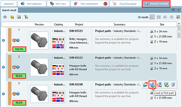
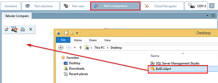
Load any native file (specific CAD file or neutral format ) into the Compare dialog [Compare].
The same function is also available via the Load 3D file [Open 3D file...]
 button. You will find a description below.
Fix description column [Pin description column] | Fix preview row [Pin preview header]
In order to always keep an eye on what is important when scrolling vertically and horizontally, it may be useful to fix the "Description " column [horizontal scrolling] or the preview line [vertical scrolling].
Call up the context menu under Tabular comparison [Tabular Compare] and activate the desired option.
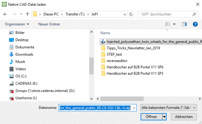
load 3D file [Open 3D file...]
:Click on the menu item Load 3D file [Open 3D file...]
.-> The Load [Load native cad file] native CAD file dialog box opens.
A variety of formats can be opened: [76]
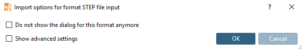
After selecting a STEP format, the Import options for STEP file input format dialog box opens.
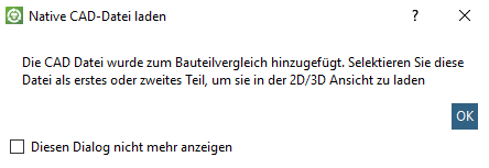
-> The Load native CAD file [Load native cad file] dialog box opens with the following message:
"The CAD file has been added to the part comparison. Select this file as the first or second part to load it in the 2D/3D view [The CAD file was added to part compare. Load the part as the first or the second project to load it in the 2D/3D view]."
Confirm with .
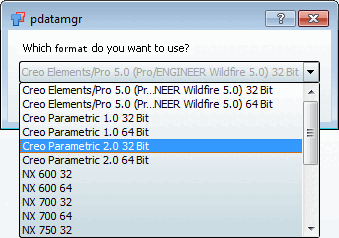
If there are ambiguities for a file extension, an additional dialog box appears.
There are ambiguities, for example, for a file extension such as
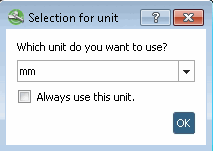
.prt, which is used by Creo Elements as well as by NX, and also for certain versions of a CAD system.The Select unit [Selection of unit] dialog box then appears.
Select the correct unit from the list box: mm, cm, dm , m, INCH, FEET, INCH/10, INCH/100
-> The file is loaded in the Tabular comparison [Tabular Compare] dialog area.
If you click on Load geometry from CAD
 the individual part or assembly selected in CAD is loaded into the dialog for the search.


[75] You can configure whether the geometric similarity should be displayed, see Section 1.7.3.5.2.1, “ Key "DisplayGeoDistances" - Tabular comparison - Display geometric similarity ” in ENTERPRISE 3Dfindit (Professional) - Administration.
[76] the display depends on the installed CAD systems