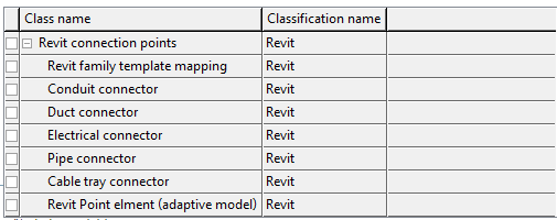
In BIM there are the following types of connection points: (See also here.)
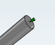
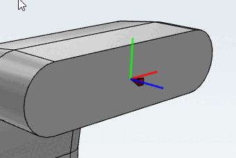
To create a connection point (for the CAD), it must be created in the 3db file at the appropriate location. The orientation of the point is important, the Z-axis must point in the direction of the pipe/duct/duct. It should be noted that some systems (e.g.: Revit) can create a connection point only at the center of a plane surface (https://en.wikipedia.org/wiki/Centroid).
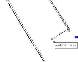
If, in rare exceptional cases (in consultation with the eCATALOG 3Dfindit project manager), no surface exists at the corresponding position in the 3db, the CAD interface creates a "dummy trigger body" (void) at this position in order to use its front surface as a reference.
This leads to the fact that the "void body" is visible in this position in the Revit Family and may cause problems.
As geometries (see Section 3.5.2.1, “Modeling Single Parts”) generally must be created exclusively with simple rule-based geometries, this scenario is very rare.
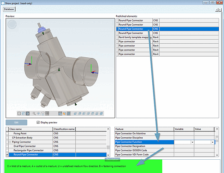
For all these connection points, a class (connection points [Connection points] ) has been created in the eCATALOG 3Dfindit classification "Revit", in which each contains the descriptive characteristics to create the point in Revit.
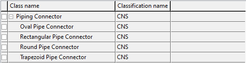
As CADENAS not only has to supply Revit with connection points, the CNS classification is successively extended by the point definitions. The class(es) "...Pipe Connector" in CNS are already completed.
![[Note]](https://webapi.partcommunity.com/service/help/latest/pages/cn/3dfindit/doc/images/note.png) | Note |
|---|---|
Currently, the CNS classification only has one equivalent for the Revit class "Pipe connector ", namely "Round Pipe Connector ". | |
The CAD interface "Revit" primarily uses the CNS "Pipe connector" definition, which is why the Revit "Pipe Connector" classes will be discontinued in the short to medium term. To ensure that the component arrives correctly with pipe connectors in the CAD (Revit), only the CNS Pipe connector definitions are to be used.
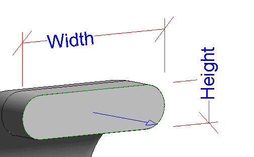
For oval pipe connection points (CNS classification), the X-axis (red) of the connection point marks the width and the Y-axis (green) the height.
A detailed description of the features of the CNS piping classification can be found under Section 5.12.13, “Piping classification ”