5.12.11.1.3. General notes
regarding part and axis orientation 5.12.11.1.3.3. Manipulation
of axes orientation (PARTproject) and part orientation
(PARTdesigner) |  |
| Prev | Next |
During the modeling process in eCATALOGsolutions there are 2 methods available to manipulate the axis orientation and the position of the component in space:
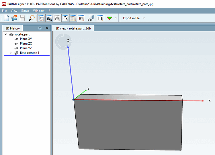
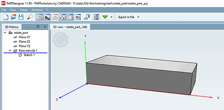
Initial situation: In eCATALOGsolutions modeled component, "faulty" with Y-axis upwards.
Request: The part shall retain its lying position within space, but the coordinate system shall get a new orientation with Z axis showing upwards.
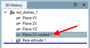
The coordinate system is realigned in PARTproject via the Coordinate axes function so that the Z-axis points upwards and the Y-axis points backwards.
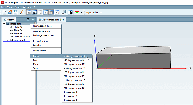
In PARTdesigner the component can be returned to its original position in space by rotating it [Rotate].
The Rotate context menu command can be found at component level in the 3D history [3D History]. After applying +90 degrees around X, the component appears in its original position again. Compare Fig. „Initial situation“.
![[Note]](https://webapi.partcommunity.com/service/help/latest/pages/cn/3dfindit/doc/images/note.png)
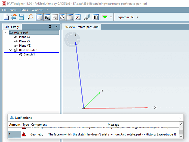
Note Rotate in PARTdesigner only works with fully modeled parts and not with Q&S parts.
The alignment of Q&S parts can be manipulated in the project file. There is a string starting with
REF1@MATRIX. In general: Calculate the rotation matrix and multiply the two matrices. There are help pages on the Internet for the calculation:http://danceswithcode.net/engineeringnotes/rotations_in_3d/demo3D/rotations_in_3d_tool.htmlorhttps://matrix.reshish.com/de/multiplication.php.The change is not in PARTdesigner but only in the PARTdataManager to see.
![PARTprojectfunction "Coordinate axes [Coordinate axes] "](https://webapi.partcommunity.com/service/help/latest/pages/cn/3dfindit/doc/resources/img/img_e29b71a3b0d943cfbae29d8735ac25b9.png)