
Frames are components that can accommodate a series of sub-connectors. They can be used to assemble defined connectors. The inserts are also often referred to as connector modules. Apart from this, frames have no major electrical functionality. The most important aspect of frames are the mounting points (the points at which the sub-connectors are inserted). See also Section 5.12.11.17, “Classification of mounting points (Mounting Point [CNS_CP|4|6] and Mounting Description [CNS_CP|4|7]) ”.
Slots have a special additional meaning in the case of frames. They not only indicate the position of a plug-in part, but also describe a virtual "connection". This is an electrical connection that does not appear in the model itself.
This is also the reason why they are classified in the supercategory "plugs".
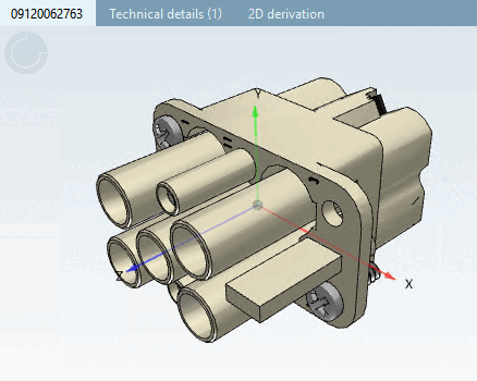
Following figure shows a plug-in module, which can be received by a frame.
Mounting descriptions for frames are modeled in the same way as for all other electrical components.
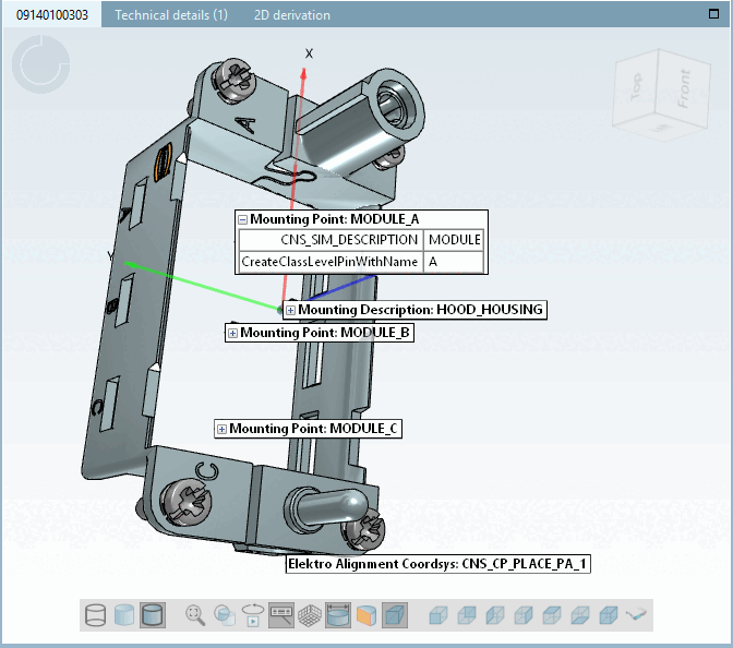
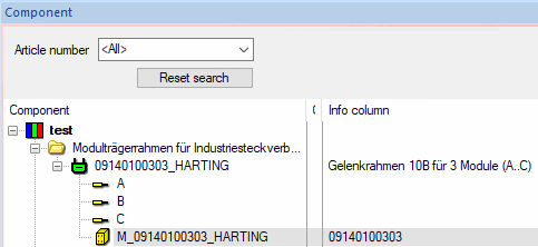
The following figure shows a frame that can itself be plugged into connection points classified as Mounting Point with feature Description and value "HOOD_HOUSING" and can accommodate 3 connectors with connection points classified as Mounting Description with feature Description and value "MODULE_A" to "MODULE_C".
Label in the 3D view in PARTdataManager: <Class name> (here Mounting Point):<Value of attribute "Description">
Label in the 3D view in PARTproject: <Class name> (here Mounting Point):<Value of attribute "Description">
Frame with 6 mounting points (description "MODULE" in each case). The Model Properties dialog shows typical slots (MODULE) into which connectors (see Fig. „Plug-in module“) can be inserted in such a frame.

Virtual connections (empty connections) are set in the CNS_CP|4|6 class with the attribute CreateClassLevelPinWithName=Pinname. If this attribute is set, the corresponding virtual connections (empty connections) are created in the interfaces in addition to the mounting points. The display name in the ECAD (e.g. Zuken E3) is the value of the "CreateClassLevelPinWithName" attribute.
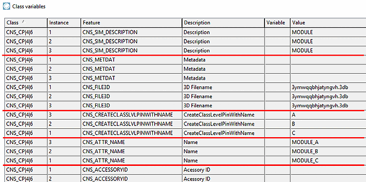
Virtual connections (dummy lines) do not contain geometry, but are implicitly linked with the respective mounting point; the only property is the name (here "A" to "C").
Harting part 09140100303 in E3: Frame with 3 virtual connections with A, B and C. The corresponding 3 slots have the description "MODULE" (see above).
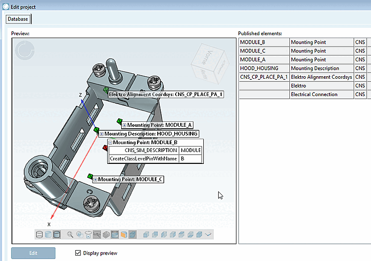
Classification of the frame from above figure in PARTsolutions. Here, "CNS_SIM_DESCRIPTION" describes the slot description, whereas the optional attribute "CreateClassLevelPinWithName" causes the system to create a virtual connection with respective name (here A) beside the slot. This attribute should be used exclusively.