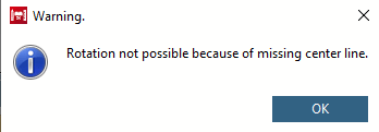
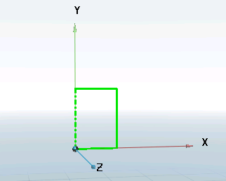
The sketch is displayed in the 3D view. An axis of rotation is selected.
Call up the context menu of the sketch using the secondary mouse button and select the command Solids [Base] -> Rotate.... [Rotate...]
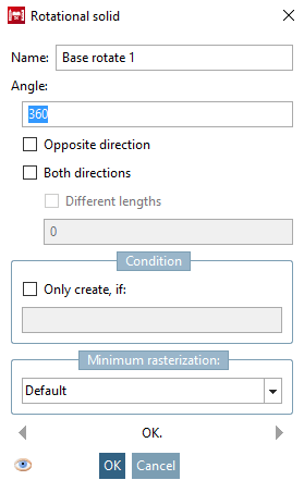
-> The Rotating body [Rotational solid] window opens.
Specify the criteria (angle [Angle], etc.) for the rotation and confirm with . Please refer to Section 7.6.2.6.1, “ Extrude... ” for an explanation of the other fields.
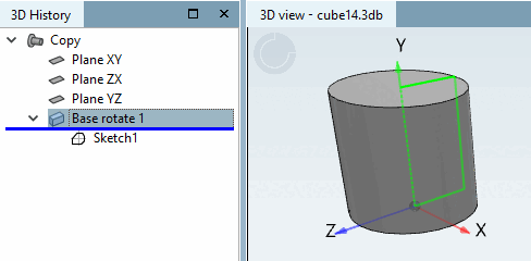
-> The directory tree in the 3D history [3D History] is extended by the item Base rotate 1.
-> In the 3D view, you can see that the two-dimensional representation of the rectangle has become a cylinder due to rotation.
![Call: Solids [Base] -> Rotate [Rotate...]..](https://webapi.partcommunity.com/service/help/latest/pages/cn/ecatalogsolutions/doc/resources/img/img_366a5c5465064b69994cea4e2400204f.png)
![[Note]](https://webapi.partcommunity.com/service/help/latest/pages/cn/ecatalogsolutions/doc/images/note.png)