![[Note]](https://webapi.partcommunity.com/service/help/latest/pages/cn/ecatalogsolutions/doc/images/note.png)
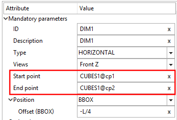
Each dimensioning must contain the following parameters:
ID is only required if a dimensioning serves as a base dimension [Base dimension] for a subsequent dimensioning. See also Section 7.16.2.2, “ Optional parameters ” -> Base dimension.
The description is automatically set and displayed in listing of dimensionings. You can adjust it as desired.
HORIZONTAL appears automatically when you create a new dimensioning. Adjust the selection in the list field if necessary. You can change the type at any time.
Under "Type" the following options are selectable:
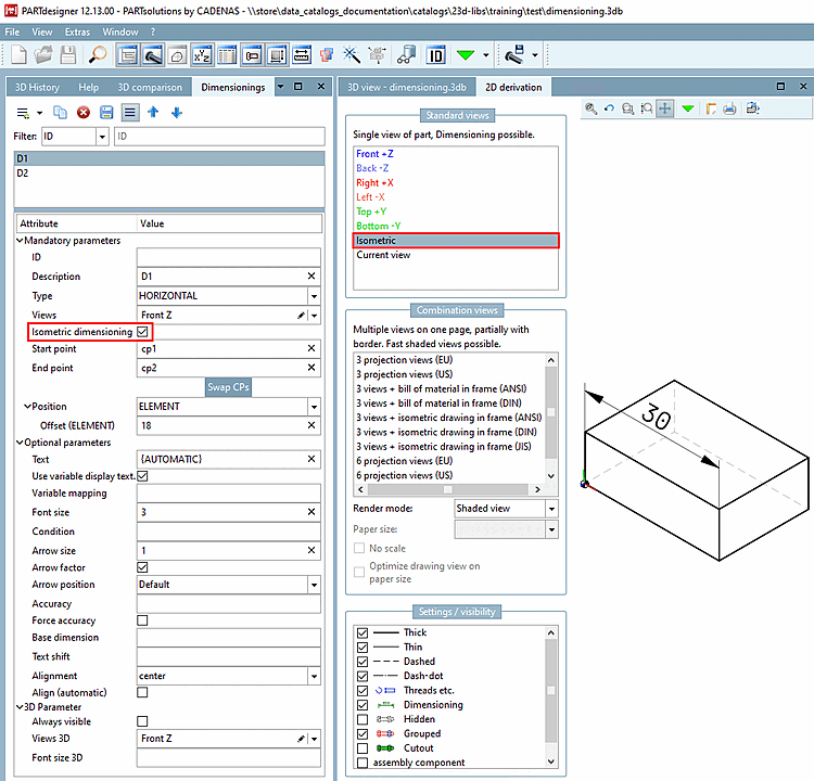
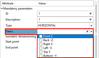
Activate the checkbox for the desired 2D views on which the dimensioning is to be displayed.
Views which contain a dimensioning, can be recognized in the 3D toolbar, by a respective icon with dimensioning lines
 .
.If you want to create a dimensioning for the 2D derivation for the "Isometric [Isometric]" view, select a standard view (Front Z in the following figure) and activate the Isometric dimensioning option.
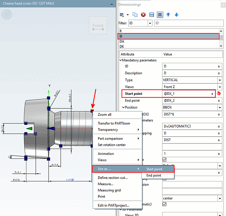
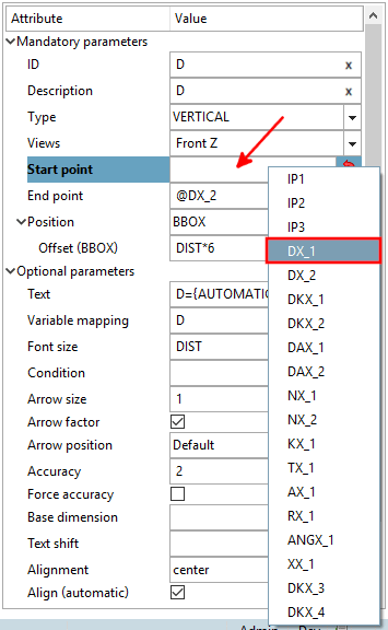
Starting point [Start point] and end point [End point]
In order to select start and end point you have different options available:
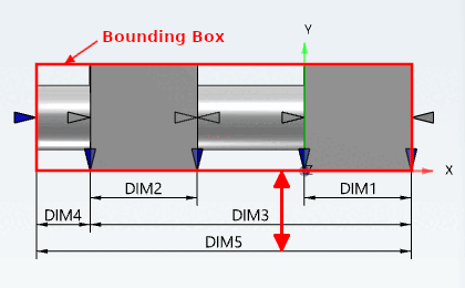
You can refer to the Bounding Box or the element or use absolute values:
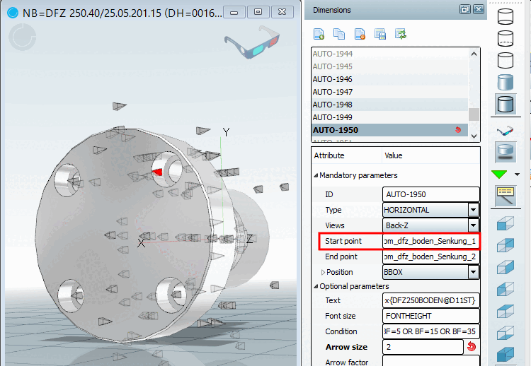
BBOX: Distance to the bounding box.
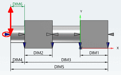
ELEMENT Distance to the element to be dimensioned itself. The reference point is the connection point.
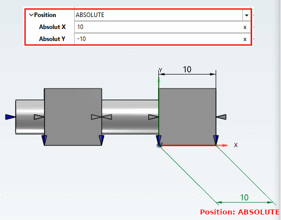
ABSOLUTE: Distance to the element to be dimensioned itself. The reference point is the zero point of the element. The input is made via the X and Y coordinates. This also allows diagonally offset dimensioning.
Distance dimension: You can use fixed values, variables or PARTdesigner expressions as a value (see Section 10.1, “PARTdesigner-Expressions ”).
Example PARTdesigner-Expression:
15*RZ500@D/20

![[Caution]](https://webapi.partcommunity.com/service/help/latest/pages/cn/ecatalogsolutions/doc/images/caution.png)