5.12.11. Classify
Electrical Parts
5.12.11.21. Classification of general connections / subcircuits
|  |
| Prev | Next |
In many situations, it is necessary to model links between different classification entities. This is modeled in a completely general form by the Inter Part Link class. It allows completely abstract connections to be established between different class instances and is not restricted to one part. An example of this would be a control cabinet with various terminals that are connected to each other by cables. In this example, the connection information describes the physical cabling in an abstract way as a logical connection.
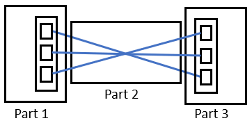
Schematic depiction of a sensor cable (plug - cable - plug) - In general both the two plugs and the cable will be separate projects. The system is not restricted in this respect.
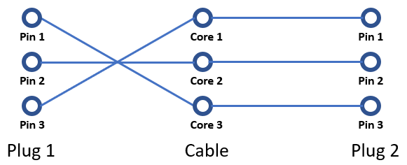
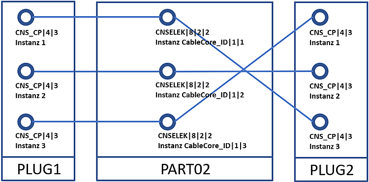
The schematic depiction from above graphic is not advantageously for our purposes. So we will consider the example in a logical depiction (analogously to circuits).
In this logical depiction individual properties like length, size, width, weight are irrelevant. In this context the only decisive is the connection information as following figure illustrates.
In the highest level of abstraction the situation can be reduced to following table:
| Pin in Part 1 | Connection to wire (left side) | Connection of wire (right side) | Pin in Part 2 | |
| 1 | 1 | Cable | 1 | 3 |
| 2 | 2 | 2 | 2 | |
| 3 | 3 | 3 | 1 |
The CNS class CNSELEK|5|7 (Inter Part Links ) works at this level. This class makes it possible to establish connections between general class instances at an abstract level (two nodes [vertex]). Note that in the example above, the individual pins are instances of the class CNS_CP|4|3 (electrical connection); the wires of the cable are instances of the class CNSELEK|8|2|2 (cable wire). For this reason, the above table contains 6 connections. I.e. a connection from the pins of part 1 to the left side of the cores as well as connections from the right side of the core to the pins of part 2.
The information to which parts an individual class instance belongs is given by "aliases" (unique identifiers). You can view them, for example, in the PARTdataManager, in the Assembly structure dialog.
![Assembly opened with "Assembly structure [Assembly structure] " function](https://webapi.partcommunity.com/service/help/latest/pages/cn/installation/doc/resources/img/img_d5cc7ed121674ad09697df95b9c34162.png)
In the example case: Part 1 has the alias "PLUG1", the cable has the alias "PART02" and the second plug has the alias "PLUG2". With these "ingredients", we can already model this situation.
The class CNSELEK|5|7 (Inter Part Link ) has the following characteristics:
Vertex 1 ASM Member ID: Localizes the part (1) of the outgoing connection via respective alias.
Vertex 1 Class Instance: Localizes the corresponding class instance in part (1)
Vertex 2 ASM Member ID: Localizes the part (2) of the incoming connection via respective alias.
Vertex 2 Class Instance: Localizes the corresponding class instance in part (2)
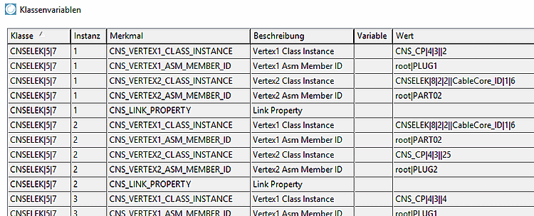
An analogous concept to XML X-Path is used for the Vertex Class Instance and Vertex Asm Member ID attributes (here the pipe symbol instead of the "/"). Once to localize the part in the assembly and then to define the corresponding class instance in the part. The only important point is that the root object (assembly) is localized via the implicit alias "root". The data from the table takes the following form:
Eight rows describe a complete connection of a pin in plug 1 with a pin in plug 2 via cable core.
The presented schema is not limited to systems such as plug-cable-plug, but can describe any connections between class instances in different parts. The meaning of such constructs depends on the specific case and is not initially defined by the Inter Part Links class.
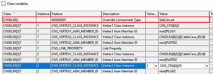
Note: For example, it is also possible to connect a class instance "living" on the assembly itself with a class instance of a part. This would look as follows:
Subcircuits directly follow the general procedure described above. However, in order to create an explicit subcircuit, the class CNSELEK|1, with the characteristic Override Component Type, must be written with the value "SubCircuit" at the assembly level. This requires consistent modeling of the inter-part links.