 |
Dimensionings can be added to projects, thus are available in PARTdataManager for the 2D derivation and are transferred to the CAD system during the export.
| Horizontal, vertical and parallel dimensioning | Radial dimensioning | Angular dimensioning | Annotations / Position numbers for bill of material |
|
|
|
|
|

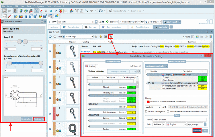
As of version 9.08 SP1 dimensioning parameters don't have to be set in a text file anymore. Now the procedure is much easier via an own dialog named "Dimensionings" in PARTdataManager [38].
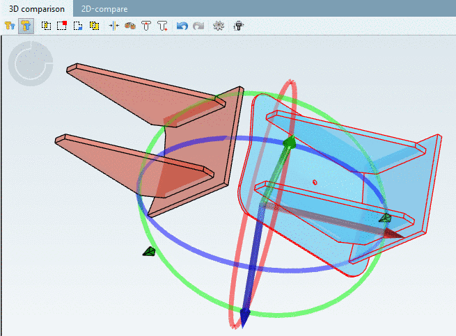
The dimensionings are created directly in the 3D view of PARTdataManager.
The user interface is a docking window.
The docking window itself consists of two dialog areas:
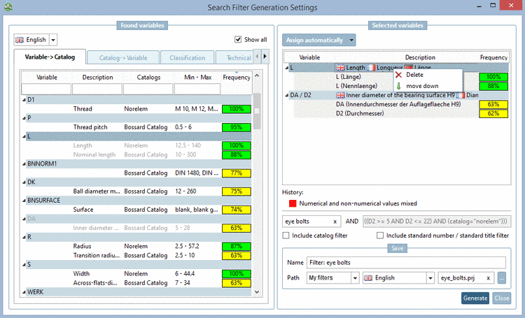
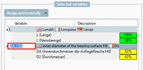
In the upper dialog area the IDs of all dimensionings of the loaded part are listed (AUTO-1000, AUTO-1001, AUTO-1002 etc.).
Clicking on a certain dimensioning, in the bottom dialog area all parameters of the selected dimensioning are listed.
Here, parameters can be added or simply be changed. Changes are visible in the 3D view at once (if all mandatory parameters are set).
On the left side of the list of dimensionings the following buttons are displayed:
–> A dialog box to select the type of dimensioning is displayed (VERTICAL, HORIZONTAL, etc.).
–> A copy of the dimensioning selected in the list is created.
–> The selected dimensioning is removed from the list; however, it can be refreshed again via button Refresh contents
 . Not until the button Save changes
  is clicked, deleting is completed and there
is no "Undo".
is clicked, deleting is completed and there
is no "Undo".–> If changes have been made directly in the file
customdimensions.txt, the user interface should be refreshed.


Possibly at first set the needed insertion points
Since the measuring points reference to connection points, they must either already be available within the part or specifically set.
Create file to save the dimensioning parameters
Create a file
customdimensions.txt.Reference file for dimensioning parameters
In the assembly configuration project file (*asmcfg.prj) and in the assembly template project file (*asmsbl.prj) create the key CUSTOMDIMENSIONS.
Key value is the name of the created file, where the dimensioning parameters are saved.
CUSTOMDIMENSIONS=customdimensions.txt
![[Note]](https://webapi.partcommunity.com/service/help/latest/pages/cn/partsolutions_user/doc/images/note.png)
Example to demonstrate the working:
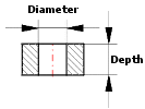
A horizontal dimensioning shall be created for a hole diameter.
In PARTdataManager, in the Part view, load the part to be dimensioned.
In PARTdataManager, open the dialog area Dimensionings by clicking on the same-named command in the context menu of the toolbars.
-> The dialog is displayed as docking area. You can detach the area via drag and drop so that it is displayed as a single window.
-> When enabling the dialog area Dimensionings dimensionings are automatically displayed in the 3D view.
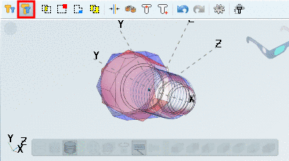
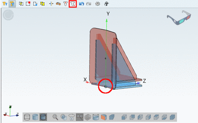
Make sure that the connection points are displayed in the 3D view.
Therefor, in the toolbar View modes, click on the button Show connection points, if needed.
Click on the button Create new dimension
 .
.-> The respective dialog box opens.
In the list field, select the option HORIZONTAL and confirm with .
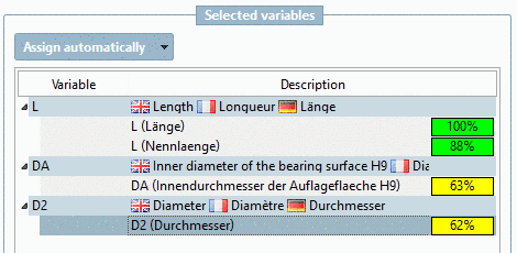
-> In the upper half of the dialog area Dimensionings a new ID is automatically created.
-> In the lower half of the dialog area Dimensionings all corresponding parameters are displayed.
Under Mandatory parameters -> Views select the desired 2D view(s), where the dimensioning has to be displayed.
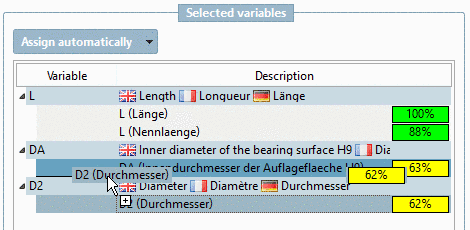
Now determine the Start point of the dimensioning.
Click into the input field of Start point and enter the name of the connection point via Ctrl+V from the clipboard.
In the list field of Position, select the value BBOX (Bounding box) and under Offset (BBOX) enter the value 10.
-> As soon as all Mandatory parameters are set, the dimensioning is shown in the 3D view.
If needed you can set Optional parameters such as Arrow size for example now.
The set dimensioning is also used for the 2D derivation.
When exporting to the CAD system the dimensioning is transferred as well.


Detailed information is found under Section 7.15, “ Docking window "Dimensionings" ” in eCATALOGsolutions Manual.