2.1.16.6.2.
Part view context menu commands
2.1.16.6.2.2. Context menu commands in the "3D view " docking window |  |
| Prev | Next |
- 2.1.16.6.2.2.1. Zoom all
- 2.1.16.6.2.2.2. Send to PARTbom/ Selected components
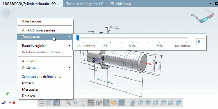
- 2.1.16.6.2.2.3. Transparency
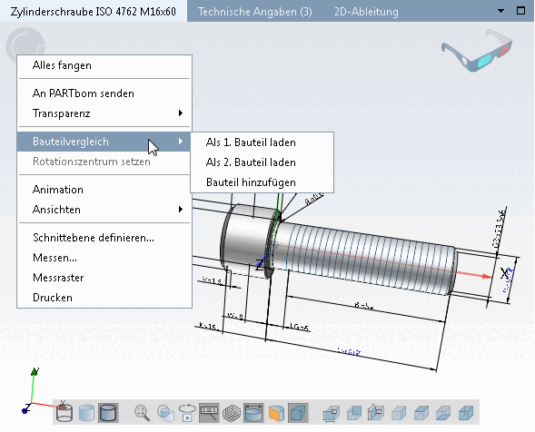
- 2.1.16.6.2.2.4. Part comparison
- 2.1.16.6.2.2.5. Animation / Set center of rotation
- 2.1.16.6.2.2.6. Views
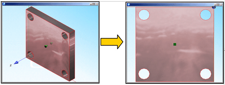
- 2.1.16.6.2.2.7. Normal to face
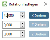
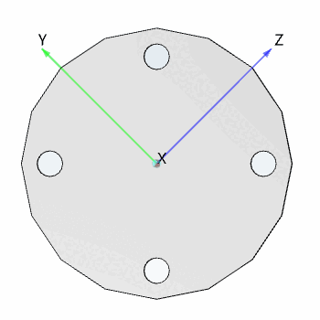
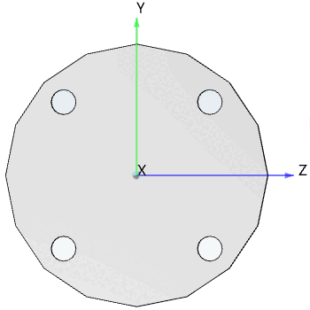
- 2.1.16.6.2.2.8. Enter rotation angle
- 2.1.16.6.2.2.9. Define section cut...
- 2.1.16.6.2.2.10. Measuring 3D parts
- 2.1.16.6.2.2.11. Measuring grid
- 2.1.16.6.2.2.12. Print
- 2.1.16.6.2.2.13. Specific commands for assemblies
![Context menu: Individual part [Single part] - 3D view](https://webapi.partcommunity.com/service/help/latest/pages/cn/partsolutions_user/doc/resources/img/img_989d51ca0f40400aa40fb6a958332471.png)
![[Note]](https://webapi.partcommunity.com/service/help/latest/pages/cn/partsolutions_user/doc/images/note.png) | Note |
|---|---|
Set the mouse button assignment under PARTdataManager - > Extras -> Settings [Settings...]... -> 3D settings -> Mouse and keyboard. Detailed information on this can be found under Section 1.3.5.4.2, “Mouse and keyboard assignments ” in ENTERPRISE 3Dfindit (Professional) - Administration. | |
With Snap all [Zoom all], you can bring the display of the component to a balanced size. The component is visible large enough, but does not protrude beyond the 3D view window when rotated. If the Exact zoom [Explicit zoom] option option is set (see Section 1.3.5.4.1, “ Operation ” in ENTERPRISE 3Dfindit (Professional) - Administration ), the display within the window is enlarged to the maximum.
In addition to the option of transferring components to your CAD system, you can also send them to PARTbom.
PARTbom (bom = bill of material) is an administration module with which you can compile parts lists for orders of components and assemblies. You can find a detailed description of PARTbom under Section 2.2, “ PARTbom ”.
You can both transfer single parts and a selection of different individual parts of an assembly:
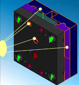
After making your selection, click on Selected components [Selected parts] -> Send to PARTbom [Transfer to PARTbom] in the context menu.
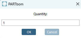
-> A dialog box for selecting the number of parts opens. Adjust the number and confirm with .
-> PARTbom then opens with the following query:
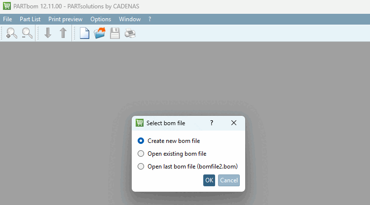
Select an option and confirm with .
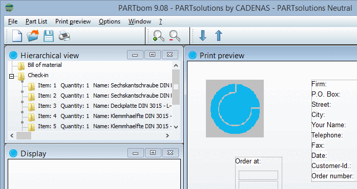
The components are entered directly in the parts list [Bill of material].
Transparency: Regulation of the transparency of a body
Using the slider, you can adjust the transparency continuously from fully visible to invisible.
Detailed information on the part comparison can be found under Section 2.1.6.10, “ Part comparison ”.
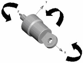
This command starts an automated rotation of the current body.
The command
exists in the context menu as well as in the 3D toolbar  .
.
Rotation takes place around the center of rotation.
Right-click on any point in the component and select the Set rotation center command (also in the context menu) to set the animation's rotation center.
To cancel the animation, click on the Animation command again or anywhere in the 3D window.
Under Views you will find 6 axis-related perspectives as well as an iso-, di- and trimetric view [Trimetric view] (perspective projection [Perspective projection] ).
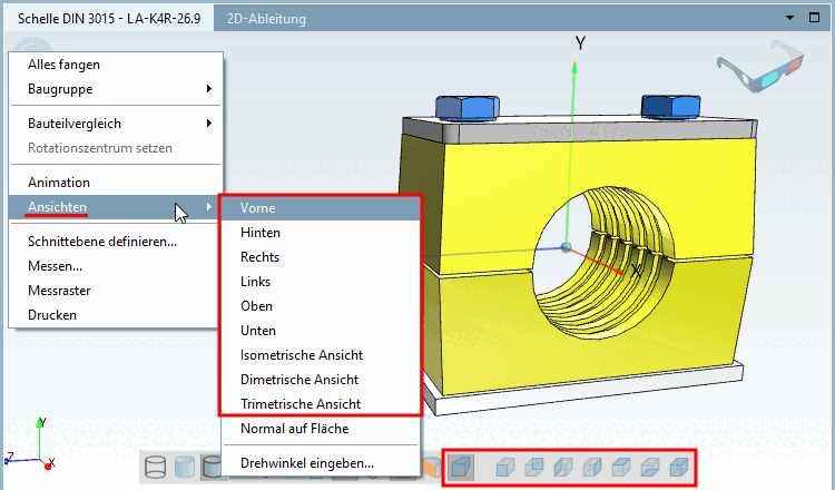
Normal on surface [Normal to face] rotates a component with the marked surface frontally (vertically) to the viewer.
opens the Specify rotation [Set rotation] window. Enter a numerical value and click on the corresponding "Axis button".
Select a sectional plane and the desired offset in relation to zero level. Depending on the algebraic sign an offset in positive or negative direction results.
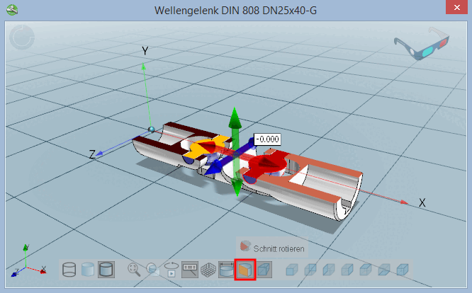
More details can be found under Section 2.1.7.6.7, “ Define section cut... ”.
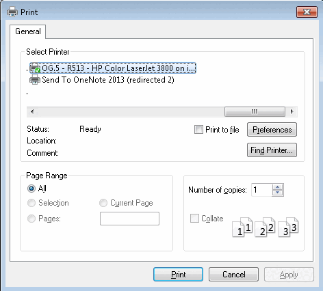
You have the option of creating a printout of the 3D view of the component/assembly.
When clicking on the command the respective settings dialog box of your operation system opens.
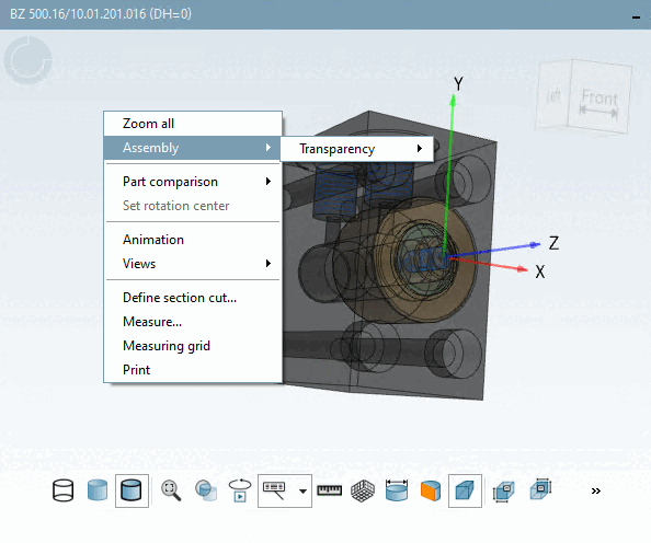
Context menus of parts and assemblies slightly differ. At assemblies the context menu depends on whether the focus is inside or outside of the assembly.
Assembly group [Assembly] (call outside the assembly group):
Opens a submenu with the Transparency function.
Transparency: See Section 2.1.16.6.2.2.3, “ Transparency ”.
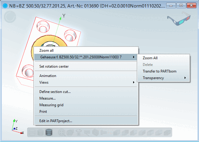
Specific name of the assembly (e.g. housing....) (call within the assembly):
Opens a submenu with the functions Snap [Zoom], Delete, Send to PARTbom [Transfer to PARTbom], Transparency.
Catch [Zoom]: Catches the selected part; in contrast to Catch all [Zoom all], which refers to the entire assembly.
Send to PARTbom [Transfer to PARTbom]: See Section 2.1.16.6.2.2.2, “ Send to PARTbom/ Selected components ”.
Transparency: See Section 2.1.16.6.2.2.3, “ Transparency ”.