!["Ellipses [Ellipses] " toolbar](https://webapi.partcommunity.com/service/help/latest/pages/cn/3dfindit/doc/resources/img/img_577889444e1d4a468b1f35c43b5489db.png)
 Ellipse by point on main axis and hull edge
point [Ellipse by point on main axis and hull edge point]
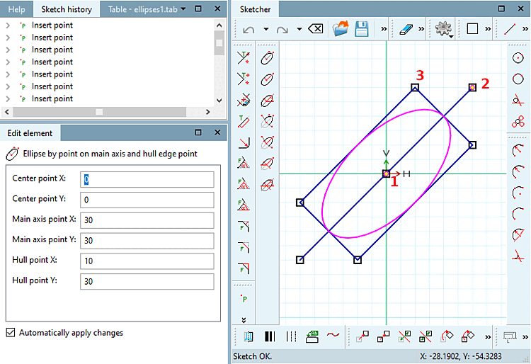
Ellipse by point on main axis and hull edge
point [Ellipse by point on main axis and hull edge point]
Click on the icon and follow the instructions displayed in the status line:
Select center point [Choose center point]: As soon as the ellipse has been created, the point coordinates are displayed under Edit element under Center point X / Center point Y.
Select point on [Select point on main axis] main axis: As soon as the ellipse has been created, the point coordinates main axis point [Main axis point] X / main axis point [Main axis point] Y are displayed under Edit element.
The ellipse's orientation results from center point and main axis point.
Select envelope point [Select hull point]: Define a corner point of the rectangle to which the ellipse is inscribed.
In the Edit element docking window, you can subsequently adjust the values or variables of the individual parameters.
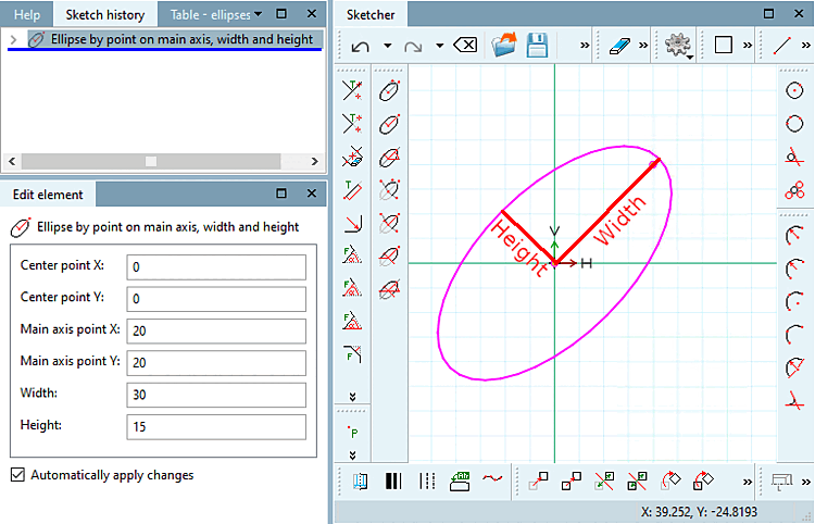
 Ellipse by point on main axis, width and
height [Ellipse by point on main axis, width and height]
Ellipse by point on main axis, width and
height [Ellipse by point on main axis, width and height]
Click on the icon and follow the instructions displayed in the status line:
Select center point [Choose center point]: As soon as the ellipse has been created, the point coordinates are displayed under Edit element under Center point X / Center point Y.
Select point on [Select point on main axis] main axis: As soon as the ellipse has been created, the point coordinates main axis point [Main axis point] X / main axis point [Main axis point] Y are displayed under Edit element.
The ellipse's orientation results from center point and main axis point.
Select dimensions [Select size]: Draw the ellipse with the desired width [Width] and height [Height].
In the Edit element docking window, you can subsequently adjust the values or variables of the individual parameters.
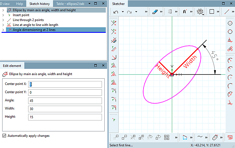
 Ellipse by main axis angle, width and
height [Ellipse by main axis angle, width and height]
Ellipse by main axis angle, width and
height [Ellipse by main axis angle, width and height]
Click on the icon and follow the instructions displayed in the status line:
Select center point [Choose center point]: As soon as the ellipse has been created, the point coordinates are displayed under Edit element under Center point X / Center point Y.
Select the angle of the [Select angle of main axis] main axis: Determine the angle in relation to the X-axis and the main axis of the ellipse.
Select dimensions [Select size]: Draw the ellipse with the desired width [Width] and height [Height].
In the Edit element docking window, you can subsequently adjust the values or variables of the individual parameters.
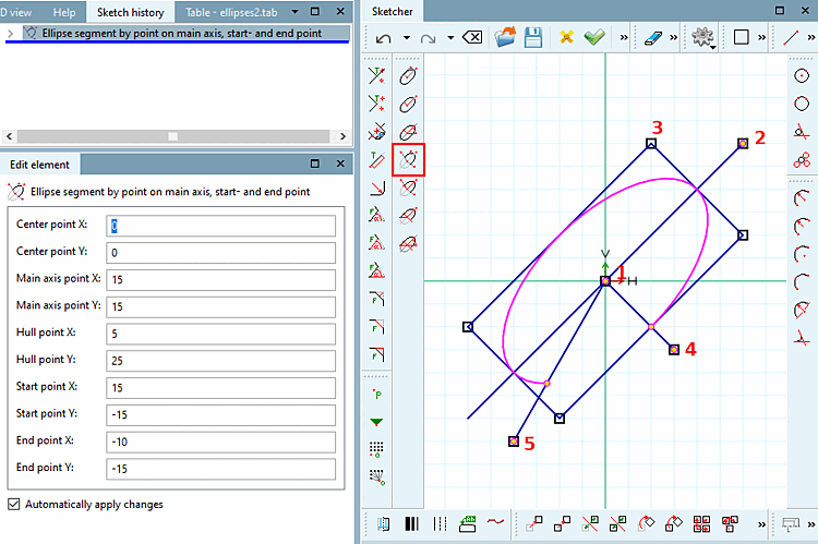
 Ellipse segment by point on main axis, start- and end
point [Ellipse segment by point on main axis, start- and end point]
Ellipse segment by point on main axis, start- and end
point [Ellipse segment by point on main axis, start- and end point]
Click on the icon and follow the instructions displayed in the status line:
Select center point [Choose center point]: As soon as the ellipse has been created, the point coordinates are displayed under Edit element under Center point X / Center point Y.
Select point on [Select point on main axis] main axis: As soon as the ellipse has been created, the point coordinates main axis point [Main axis point] X / main axis point [Main axis point] Y are displayed under Edit element.
The ellipse's orientation results from center point and main axis point.
Select envelope point [Select hull point]: Define a corner point of the rectangle to which the ellipse is inscribed.
Select the starting point [Choose start point]: The ellipse segment begins at the intersection of the line between the center of the ellipse and the starting point and the ellipse.
Select end point: The ellipse segment ends at the intersection of the line between the ellipse center end point and the ellipse.
-> The segment located counterclockwise between 4) and 5) remains.
In the Edit element docking window, you can subsequently adjust the values or variables of the individual parameters.
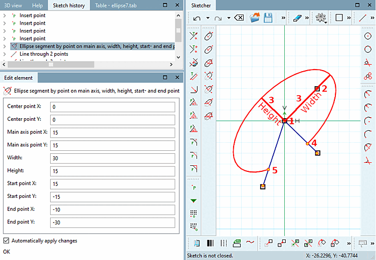
 Ellipse segment by point on main axis, width, height,
start- and end point [Ellipse segment by point on main axis, width, height, start- and end point]
Ellipse segment by point on main axis, width, height,
start- and end point [Ellipse segment by point on main axis, width, height, start- and end point]
Click on the icon and follow the instructions displayed in the status line:
Select center point [Choose center point]: As soon as the ellipse has been created, the point coordinates are displayed under Edit element under Center point X / Center point Y.
Select point on [Select point on main axis] main axis: As soon as the ellipse has been created, the point coordinates main axis point [Main axis point] X / main axis point [Main axis point] Y are displayed under Edit element.
The ellipse's orientation results from center point and main axis point.
Select dimensions [Select size]: Draw the ellipse with the desired width [Width] and height [Height].
Select the starting point [Choose start point]: The ellipse segment begins at the intersection of the line between the center of the ellipse and the starting point and the ellipse.
Select end point: The ellipse segment ends at the intersection of the line between the ellipse center end point and the ellipse.
-> The segment located counterclockwise between 4) and 5) remains!
In the Edit element docking window, you can subsequently adjust the values or variables of the individual parameters.
 Ellipse segment by point on main axis, width, height,
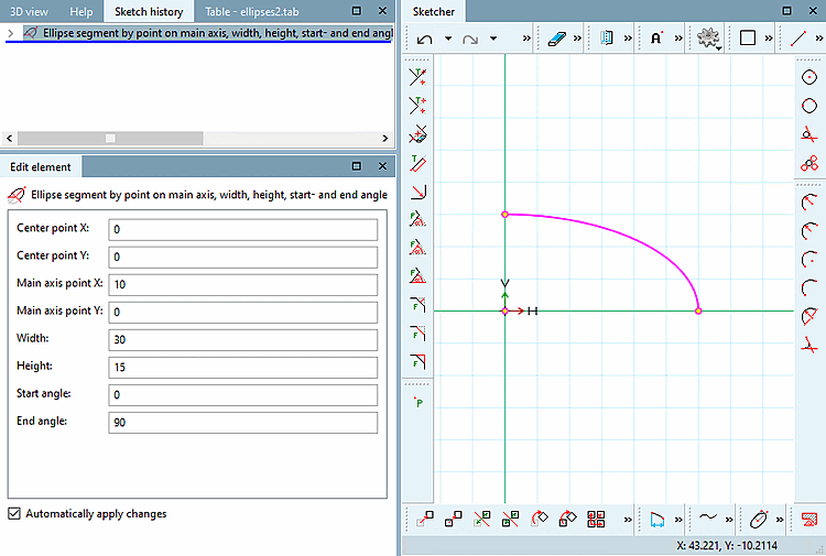
start- and end angle [Ellipse segment by point on main axis, width, height, start- and end angle]
Ellipse segment by point on main axis, width, height,
start- and end angle [Ellipse segment by point on main axis, width, height, start- and end angle]
Click on the icon and follow the instructions displayed in the status line:
Select center point [Choose center point]: The selected point is displayed in the dialog under Centre point X / Centre point Y.
Select point on [Select point on main axis] main axis: The selected point is displayed in the dialog under Main axis point X / Main axis point Y.
The ellipse's orientation results from center point and main axis point.
Select dimensions [Select size]: Draw the ellipse with the desired width [Width] and height [Height].
The start angle [Start angle] and end angle [End angle] are relative to the main axis. The angle is applied counterclockwise as usual.
In the Edit element docking window, you can subsequently adjust the values or variables of the individual parameters.
![[Note]](https://webapi.partcommunity.com/service/help/latest/pages/cn/3dfindit/doc/images/note.png)
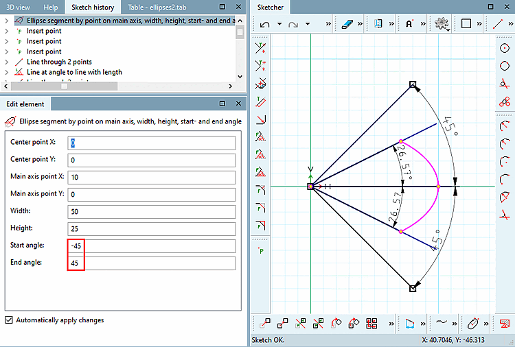
Note For ellipse segments that do not reach their max./min. extension (values of the main and secondary axis), the actual values in the sketch regarding width [Width] / height [Height] and start angle [Start angle] / end angle [End angle] are not correct due to the internal calculation method.
An arc is created with the entered start angle [Start angle] and end angle [End angle].
Now the circular arc is compressed/stretched in order to bring it in the form of an ellipse.
In doing so also start angle and end angle are compressed.
So the angle originally stated is not the one shown in the sketch. Also width and hight of the ellipse segment are divergent. See Fig. „Ellipse segment: divergent values in the sketch“. (The lines pointing out the angles with 45 degree are only for clarification.)
 Ellipse segment by main axis angle, width, height,
start- and end angle [Ellipse segment by main axis angle, width, height, start- and end angle]
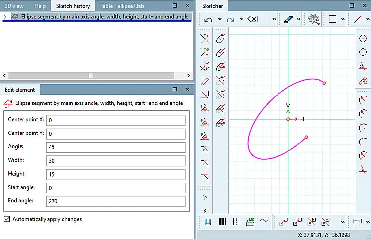
Ellipse segment by main axis angle, width, height,
start- and end angle [Ellipse segment by main axis angle, width, height, start- and end angle]
Click on the icon and follow the instructions displayed in the status line:
Select center point [Choose center point]: The selected point is displayed in the dialog under Centre point X / Centre point Y.
Select the angle of the [Select angle of main axis] main axis: Determine the angle in relation to the X-axis and the main axis of the ellipse.
Select dimensions [Select size]: Draw the ellipse with the desired width [Width] and height [Height].
The start angle [Start angle] and end angle [End angle] are relative to the main axis. The angle is applied counterclockwise as usual.
In the Edit element docking window, you can subsequently adjust the values or variables of the individual parameters.
Note The under
Ellipseg. Pkt. on main axis, width and height, start and end angles [Ellipse segment by point on main axis, width, height, start- and end angle] also applies here. See note above.