1.6. CAD
encompassing reference of all menu commands
1.6.2.
Insert from the standard and purchased parts library via "PARTdataManager" |  |
| Prev | Next |
The following describes how to insert a part from PARTdataManager into your 3D CAD system.
![[Note]](https://webapi.partcommunity.com/service/help/latest/pages/cn/partsolutions_user/doc/images/note.png) | Note |
|---|---|
This is the description of the default procedure. For some CAD systems you can find further information in the CAD specific chapter. | |
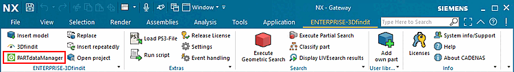
In the 3Dfindit menu, click PARTdataManager
 or Insert Model [Insert model]
 .
.
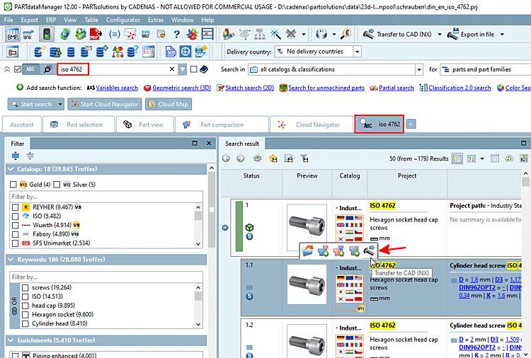
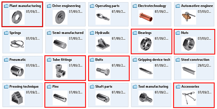
Select the desired component in the part selection [Part selection]. [8]
Specify the desired characteristic in the parts view [Part view].
Click on
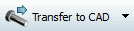 .[9]-> The display returns to the CAD system.
If you performed a search, you can directly export from the search results.
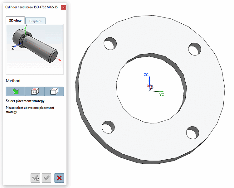
The 3Dfindit placement dialog appears in the CAD system.
-> The 3D view in the placement dialog now shows the possible connection points. If several connection points are possible, corresponding information is displayed in the placement dialog.
-> In the placement dialog on the Graphics tab page, you will find 3D images of the component or technical views (if available).
-> The following buttons are now displayed in the placement dialog:

Place multiple times [Place multiple] (and leave dialog open) 
Place once (and close dialog) 
Close dialog (without placement) Multiple placement: Activating the checkbox enables direct, repeated placement in the CAD without having to use the Multiple placement [Place multiple]
button each time.
[10]
![PARTdataManager - Parts selection [Part selection]](https://webapi.partcommunity.com/service/help/latest/pages/cn/partsolutions_user/doc/resources/img/img_5fedd8b17821451282a41bc424b8b844.png)
![PARTdataManager - Parts view [Part view]](https://webapi.partcommunity.com/service/help/latest/pages/cn/partsolutions_user/doc/resources/img/img_264396d76ffb402ab00193ef44312418.png)


[8] You can find a detailed description of PARTdataManager at Section 2.1, “ PARTdataManager ”.
[9] You can also export the component using "Export to file [Export in file] ". Detailed information on this can be found under Section 2.1.9, “ Export to various file formats (without 3Dfindit interface) ”.
[10] In certain CAD systems, the function is available for all placement methods, in others only for the standard CAD placement method. If the method is not available, the checkbox appears grayed out.