1.6. CAD
encompassing reference of all menu commands
1.6.4.
Insert model (2D) from the standard and purchased parts library
|  |
| Prev | Next |
The following describes how to insert 2D individual parts from the standard and purchased parts library [Standard and supplier parts library] into your CAD system.
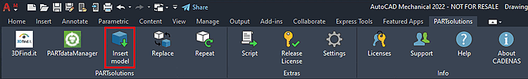
In the 3Dfindit menu, click
 Insert
model [Insert model]. [12]
Insert
model [Insert model]. [12]
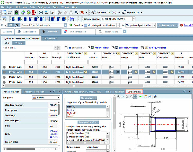
Select the desired component in the part selection [Part selection]. [13]
Specify the desired characteristic in the parts view [Part view].
Creating the 2D deriv [2D derivation] ation
To do so, you have the following options:
Click on the 2D derivation button
 .
.-> The 2D derivation docking window opens.
Select a view.[14]
Alternatively, you can skip calling up the 2D view and directly click Transfer to CAD
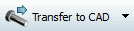 click.
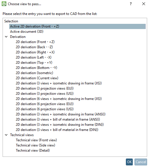
The Select view to be transferred [Choose view to pass...] dialog box then opens.... [Choose view to pass...]
The following views are available in the Select view to be transferred. [Choose view to pass...].. dialog box. dialog box:
Click on the button
(option a) or confirm with (option b)[15]-> The view switches back to the CAD system.Insert the part and/or assembly with the placement method of your CAD system.
![PARTdataManager - Parts selection [Part selection]](https://webapi.partcommunity.com/service/help/latest/pages/cn/partsolutions_user/doc/resources/img/img_5fedd8b17821451282a41bc424b8b844.png)
![PARTdataManager - Parts view [Part view]](https://webapi.partcommunity.com/service/help/latest/pages/cn/partsolutions_user/doc/resources/img/img_264396d76ffb402ab00193ef44312418.png)
![[Note]](https://webapi.partcommunity.com/service/help/latest/pages/cn/partsolutions_user/doc/images/note.png)
![PARTdataManager -> Extras menu -> Settings [Settings...]..](https://webapi.partcommunity.com/service/help/latest/pages/cn/partsolutions_user/doc/resources/img/img_bc50619b0dba4e91a7a3b97a5f988b8d.png)
[12] With AutoCAD, for example, Insert by default model [Insert model] displayed. Whether used in CAD 2D or 3D mode depends on whether the 2D derivative is previously created in PSOL became. The config can be used to switch to the button display to Insert 2D.
Also note the setting under PARTdataManager -> Extras Menu -> Settings... -> Transfer to CAD. [Export to CAD]
[13] You can find a detailed description of PARTdataManager at Section 2.1, “ PARTdataManager ”.
[14] Detailed information on the 2D view can be found under Section 2.1.10, “ Create 2D derivation ”.
[15] You can also export the component using "Export to file [Export in file] ". Detailed information on this can be found under Section 2.1.9, “ Export to various file formats (without 3Dfindit interface) ”.