
- 3.4.1. AutoCAD
- 3.4.2. Catia V5 Macro
- 3.4.3. Creo Elements/Direct Modeling
- 3.4.4. Creo Parametric
- 3.4.5. Autodesk Fusion 360
- 3.4.6. Inventor
- 3.4.7. NX
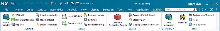
- 3.4.7.1. Standard information
- 3.4.7.2. Additional information
- 3.4.7.2.1. First start
- 3.4.7.2.2. Replace component via dimensions
- 3.4.7.2.3. Insert 3D - Component placement
- 3.4.7.2.4. Mapping of thread standards
- 3.4.7.2.5. Blend feature
- 3.4.7.2.6. Pattern features
- 3.4.7.2.7. Add 3Dfindit commands to the NX context menu
- 3.4.7.2.8. Physical properties from 3Dfindit
- 3.4.7.2.9. NX: Testing 3Dfindit parts in the Mechatronics Concept Designer
- 3.4.7.2.10. NX - Attributes: Units, category and Expression formula readable and optionally writable
- 3.4.7.2.11. Piping
- 3.4.7.3. Administration
- 3.4.8. Revit
- 3.4.9. Solid Edge
- 3.4.10. SolidWorks
In the following sections, all CAD systems for which interfaces are currently available are listed in alphabetical order with their commands/menu items.
Each CAD section is structured as follows:
At the beginning you will find a matrix showing the available functions of the individual interfaces.


The corresponding legend is shown in the next table.
| Short note | ||

|
If no application has been started yet, the 3Dfindit client starts, if this is not possible, PARTdataManager starts, if an application is already running, the user is asked whether he wants to start 3Dfindit or PARTdataManager. | |

|
Start of PARTdataManager and transfer of 2D components from PARTsolutions to CAD | |

|
3Dfindit: Visual search engine for 3D manufacturer components | |

|
PARTdataManager: Transfer of 3D components from PARTsolutions to CAD | |

| ||

| ||

|
The system checks whether the selected assembly element originates from 3Dfindit. | |

|
The favorites lists are displayed. Details can be found here. |
The following figure shows the functions using NX as an example:
| Short note | ||

| ||

| ||

|
Explicit release of the 3Dfindit export license (only relevant for floating licensing). | |

|
Call PARTadmin to make changes to the interface configuration file | |

| Event handling |
Special settings for LIVEsearch. See Section 3.5.14, “LIVEsearch ”-> "Automatic call of LIVEsearch" |
![[Note]](https://webapi.partcommunity.com/service/help/latest/pages/cn/3dfindit/doc/images/note.png) | Note |
|---|---|
You can set which functions are to be displayed in the menu and toolbar. Information on this can be found under Section 3.2.2, “Design of 3Dfindit interface menu and toolbar ” in ENTERPRISE 3Dfindit (Professional) - Administration. | |